
Integrated power failure indication and status monitoring device

A state monitoring device and power failure technology, which is applied in the direction of measuring device, fault location, measuring power, etc., can solve the problems of the influence of intelligent distribution network operation, the problem of motor feedback power transmission, and the large instantaneous amplitude of current, so as to save power outages. Retrofit time and solve the tedious effect of installing equipment

Active Publication Date: 2015-11-11
STATE GRID CORP OF CHINA +1
View PDF12 Cites 0 Cited by
  • Summary
  • Abstract
  • Description
  • Claims
  • Application Information

AI Technical Summary

Problems solved by technology

But the existing fault indicator has the following defects: 1. The working power of the fault indicator. There are two ways for the working power of the traditional fault indicator. The first is to use a lithium battery to provide power, and the battery power can usually be used for 3 -4 years, if the service life of the battery is exceeded, there will be situations such as failure to work or false alarms, which will affect the operation of the smart distribution network, and the number of distribution equipment is tens of thousands, which is very large, and replacing the battery is a waste of time. Time-consuming
The second is to use the current of the primary line of the power grid to extract the working power. This kind of working power requires that the current on the primary line cannot be less than its minimum operating current, but it cannot be used on some small line branches and lines with small loads.
2. Maloperation and refusal of the fault indicator. For short-circuit faults, the accuracy of the current indicator cannot reach 100%, and sometimes it will malfunction. The main reasons are: a. Sometimes there will be a sudden surge current during operation and the switching of large load equipment on the power consumption side, causing the fault indicator to malfunction; The machine sends power to the loop formed by the short-circuit point, or the reverse current generated by the charging and discharging of the capacitor. The current amplitude is very large at an instant, and then decays to zero.
In addition, in the transformation of distribution network in urban built-up areas, the allowable power outage time is very limited, and automation equipment needs to be installed quickly. Therefore, installing and connecting a large number of transformers and sensor equipment on cables is not only very cumbersome and error-prone, but also takes up a lot of energy. On-site power outage time
Therefore, the existing distribution automation transformation technology is insufficient

Method used


Image

  • Integrated power failure indication and status monitoring device

Examples


Embodiment Construction

[0014] In order to further understand the content, characteristics and effects of the present invention, the following examples are given, and detailed descriptions are given below with reference to the accompanying drawings. It should be noted that this embodiment is descriptive, not restrictive, and cannot thereby limit the protection scope of the present invention.

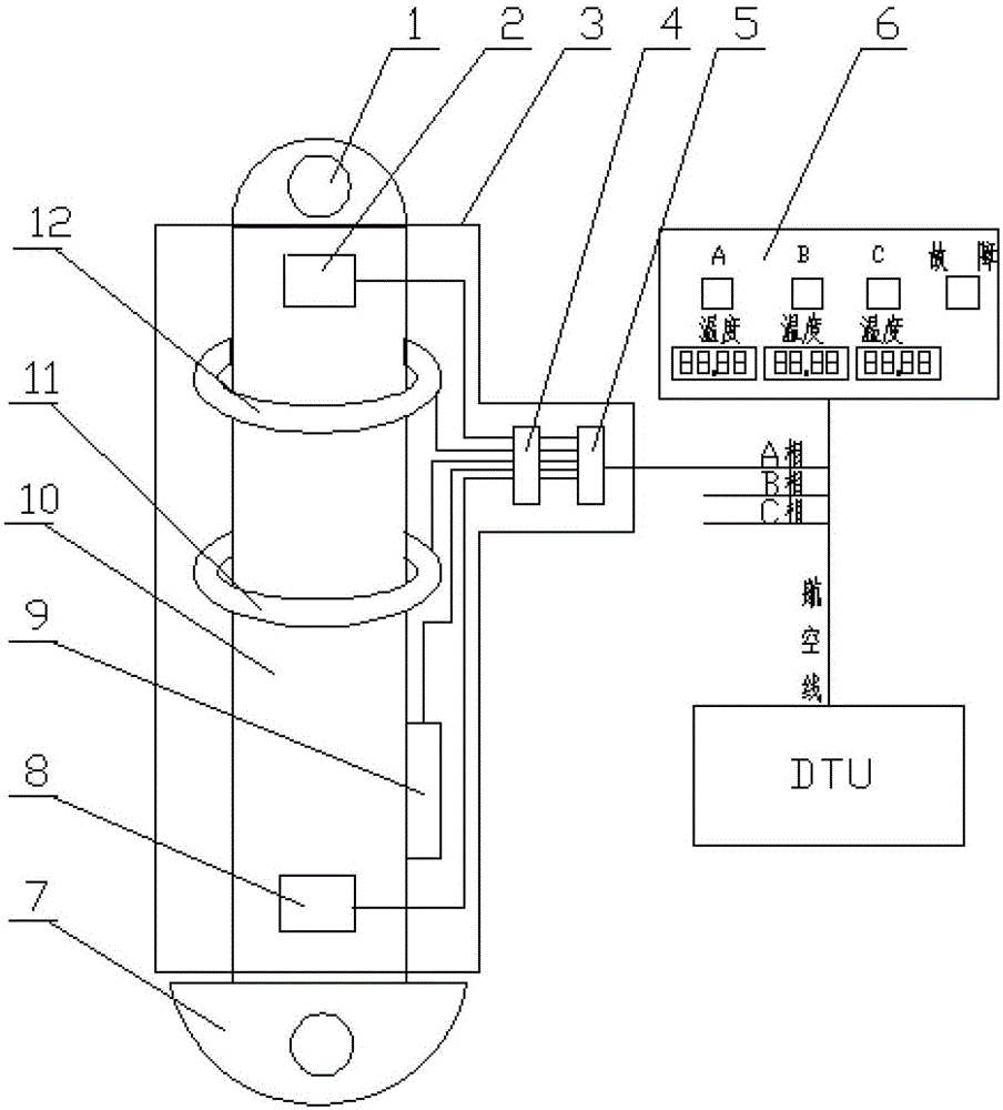
[0015] An integrated power failure indication and state monitoring device, including a copper bar 10, a temperature sensor 2 (8), a current transformer 12, a Rogowski coil 11, a point indicator 9, a DTU, and a display panel 6. The copper bar is A cylindrical copper bar, the outer edge of which is covered with an insulating sheath; the upper end 1 of the copper bar is connected to the copper bar of the switch cabinet, and the lower end 7 is connected to the cable, which are respectively tightened with large screws and nuts (not shown in the drawings of this embodiment) , Two temperature sensors are respectively ...


PUM


Abstract

The invention relates to an integrated power failure indication and condition monitoring device. The device comprises a copper bar, temperature sensors, a current transformer, a Rogowski coil, a potential indicator, a DTU (Data Terminal Unit) and a control panel and is characterized in that the copper bar is a cylindrical copper bar coated with an insulation sheath; the upper end of the copper bar is connected with that of a switch cabinet, the lower end of the copper bar is connected with a cable, and the upper end and the lower end of the copper bar are tightened through big screws and nuts respectively; the two temperature sensors are mounted at the upper end and the lower end of the copper bar respectively; the Rogowski coil and the voltage sensor are mounted in the middle of the copper bar; the potential indicator is also mounted on the copper bar; and the whole device is sleeved with an insulating housing. The device integrates secondary monitoring equipment and primary equipment into one module, so that only electrical connection of the primary equipment with a simple structure is needed while on-site mounting of the complex secondary equipment is not needed, thereby saving a great amount of power failure reformation time; and meanwhile, inconvenience caused by battery replacement of the failure indicator is solved, and the failure indicator is connected with an in-station direct current supply, which ensures that the failure indicator can run normally for a long time.

Description

technical field [0001] The invention belongs to the technical field of power distribution network automation, and relates to high-reliability identification of power equipment failures and real-time monitoring of power equipment hidden dangers, in particular to an integrated power failure indication and state monitoring device. Background technique [0002] As an important tool for finding fault points on power lines, fault indicators are widely used in the power industry. The fault indicator indicates the outgoing line, branch and section where the fault is located by detecting the fault current of the distribution line, which provides great convenience for finding the fault. Although the level of distribution automation in developed countries is very high, the main way to find faults in distribution lines still relies on fault indicators. But the existing fault indicator has the following defects: 1. The working power of the fault indicator. There are two ways for the wor...

Claims


Application Information

Patent Timeline
Patent Type & Authority Patents(China)
IPC IPC(8): G01R31/08G01R31/02
Inventor 刘畅都志军刘荣浩沈宾刘丽瑶唐策严崇松
Owner STATE GRID CORP OF CHINA
Learn More