
Electronic access control system

An electronic access control and electronic door lock technology, which is applied to instruments, time registers, and individual input/output registers, etc., can solve the problems of inability to realize access control remote alarm, remote control, and automatic switch, etc., and achieve good results. The effect of the anti-theft effect

Inactive Publication Date: 2013-08-14
苏州数伦科技有限公司
View PDF7 Cites 26 Cited by
  • Summary
  • Abstract
  • Description
  • Claims
  • Application Information

AI Technical Summary

Problems solved by technology

[0003] The invention effectively solves the technical problems in the prior art that the access control system cannot automatically identify the identity of the visitor, cannot automatically switch on and off according to the visitor, cannot be controlled by remote control, and cannot realize the remote alarm of the access control system.

Method used


Image

  • Electronic access control system
  • Electronic access control system

Examples


Embodiment 1

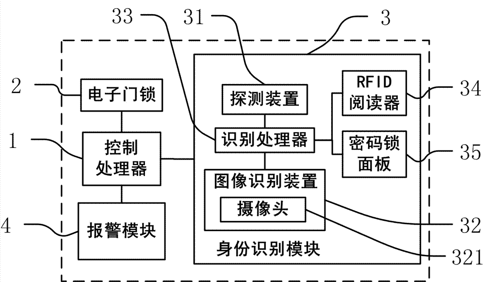
[0034] figure 1 It is a structural schematic diagram of Embodiment 1 of the present invention, figure 1 The electronic access control system described in, including:

[0035] A control processor 1, including a processor and its peripheral circuit modules, for sending control instructions;

[0036] An electronic door lock 2, connected to the control processor 1, for receiving and executing control instructions from the control processor 1;

[0037] An identity recognition module 3, connected to the control processor 1, used to identify the identity information of people outside the door;

[0038] An alarm module 4, connected to the control processor 1, for sending out alarm information.

[0039] Identity module 3 includes:

[0040] At least one detection device 31 for detecting whether there is anyone outside the door;

[0041] At least one image recognition device 32 for collecting images or videos of people outside the door;

[0042] A recognition processor 33 is respec...

Embodiment 2

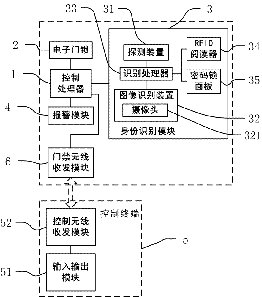
[0047] figure 2 It is a structural schematic diagram of Embodiment 2 of the present invention, and most of the technical solutions of Embodiment 2 are the same as Embodiment 1, and its distinguishing technical features are: figure 1 The electronic access control system described in also includes a control terminal 5 connected to the control processor 1 .

[0048] Control terminal 5 comprises an input and output module 51, and input and output module 51 comprises:

[0049] a keyboard (not shown in the figure), connected to the control processor 1, for inputting control commands to the control processor 1; and

[0050] A display screen (not shown in the figure), connected to the control processor 1, is used to output the working status data of the electronic door lock 2 and the identity information data of the person outside the door.

[0051] The control terminal 5 includes an input-output module 51; the input-output module 51 includes:

[0052] A touch screen (not shown in...


PUM


Abstract

The invention discloses an electronic access control system. The electronic access control system comprises a control processor and an electronic lock, and also comprises an identity identification module and an alarm module, wherein the identity identification module comprises at least one detection device, at least one image identification device and an identification processor. The electronic access control system has the advantages of being capable of automatically identifying the identity of a visitor outside the room, and automatically identifying whether to open the door or not, and having no need of monitoring from an owner of the room; and the electronic access control system also has the advantages of being capable of feeding back the identify information of the visitor outside the door in time, and allowing the owner to determine whether to open the door or not, and controlling the switching on and off of the access control system in a remote control manner. The electronic access control system has an excellent anti-theft effect, can realize the remote alarming function, and enables an owner outside the room to know the safety condition at home.

Description

technical field [0001] The invention relates to an electronic access control system. Background technique [0002] The commonly used access control system in the prior art is designed to protect home security, and the access control system itself does not have a visitor identification function or a remote control operation function. In the use of home access control, the owner needs to identify the identity of the visitor outside the door, and then open the door by himself after confirming that the door can be opened; if the room is relatively large, or the owner is inconvenient, and cannot confirm the identity of the visitor, the access control cannot be opened in time. In public places, such as libraries and access control systems, although they have identification functions (using reader ID card identification), their security protection functions are poor, and a large number of staff are often required to be responsible for security during use, and of course they do not ...

Claims


Application Information

Patent Timeline
IPC IPC(8): G07C9/00
Inventor 祝辰
Owner 苏州数伦科技有限公司
Learn More