Voltage protection method for interphase short circuit faults of electric transmission line

A transmission line, interphase short circuit technology, applied in emergency protection circuit devices, electrical components and other directions, can solve the problems of load transfer, power grid security safety hazards, impedance distance protection misoperation or refusal to operate, etc., to achieve high action sensitivity and protection range. The effect of stable, correct and reliable action

Active Publication Date: 2013-08-14
STATE GRID CORP OF CHINA +2
View PDF4 Cites 3 Cited by
  • Summary
  • Abstract
  • Description
  • Claims
  • Application Information

AI Technical Summary

Problems solved by technology

[0002] The additional impedance generated by the transition resistance will seriously affect the action performance of the impedance distance protection
If the additional impedance generated by the transition resistance is resistive and inductive, it is easy to cause the impedance distance protection to refuse to operate when there is a short-circuit fault between phases in the protection zone; The distance protection action produces overtaking
[0003] High/super/extreme voltage AC transmission lines are often also heavy-duty transmission lines. Heavy-load currents will cause the impedance distance protection to malfunction or refuse to ope

Method used


Image

  • Voltage protection method for interphase short circuit faults of electric transmission line
  • Voltage protection method for interphase short circuit faults of electric transmission line
  • Voltage protection method for interphase short circuit faults of electric transmission line

Examples


Embodiment Construction

[0016] The technical solution of the present invention will be further described in detail according to the accompanying drawings.

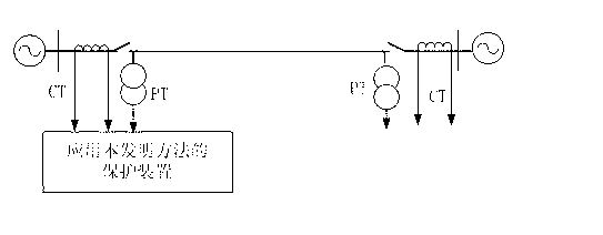
[0017] figure 1 It is a schematic diagram of the line transmission system applying the present invention. figure 1 Among them, PT is a voltage transformer, and CT is a current transformer. The protection device samples the voltage waveform of the voltage transformer PT and the current waveform of the current transformer CT at the transmission line protection installation to obtain the instantaneous voltage and current values, and uses the Fourier algorithm to calculate the fault phase-to-phase voltage at the transmission line protection installation Fault phase current and negative sequence current between fault phases Among them, φφ=AB, BC, CA phase.

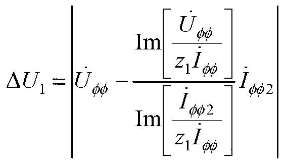
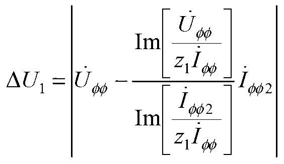
[0018] The protection device calculates the voltage of the phase-to-phase short-circuit fault point Among them, z 1 is the positive sequence impedance of the transmission line per unit l...


PUM


Abstract

The invention discloses a voltage protection method for interphase short circuit faults of an electric transmission line. The voltage protection method comprises the following steps: calculating the voltage of an interphase short circuit fault point by fault interphase electric capacity at an electric transmission line protection mounting part, using the fault interphase voltage of the electric transmission line protection mounting part to minus the voltage of the interphase short circuit fault point to obtain a voltage drop from the electric transmission line protection mounting part to the interphase short circuit fault point, multiplying the voltage drop of a unit length electric transmission line by the protection setting range to obtain a voltage drop from the electric transmission line protection mounting part to the protection setting range, and judging whether the argument that the amplitude of the voltage drop from the electric transmission line protection mounting part to the interphase short circuit fault point is smaller than that of the voltage drop from the electric transmission line protection mounting part to the protection setting range is tenable, if yes, an action tripping signal is give out by a protection device. The method solves the problem of the influence of transition resistance and load current on the protection action performance, and when interphase high-resistance short circuit faults occur to the electric transmission line, the method can act correctly and reliably, the action sensitivity is high, and the protection range is stable.

Description

technical field [0001] The invention relates to the technical field of electric power system relay protection, in particular to a method for protecting transmission line phase-to-phase short-circuit fault voltage. Background technique [0002] The additional impedance generated by the transition resistance will seriously affect the action performance of the impedance distance protection. If the additional impedance generated by the transition resistance is resistive and inductive, it is easy to cause the impedance distance protection to refuse to operate when there is a short-circuit fault between phases in the protection zone; The distance protection action produces overtaking. [0003] High / super / extreme voltage AC transmission lines are often also heavy-duty transmission lines. Heavy-load currents will cause impedance distance protection to malfunction or refuse to operate. The impact of heavy-load current on the performance of impedance distance protection cannot be ign...

Claims


Application Information

Patent Timeline
IPC IPC(8): H02H7/26
Inventor 林富洪
Owner STATE GRID CORP OF CHINA
Why Eureka
Try Eureka