Clamp

A fixture and slider technology, applied in the field of machinery, can solve the problem that the fixture is not universal, and achieve the effect of rotation and horizontal and vertical movement

Active Publication Date: 2013-08-21
广东健齿生物科技有限公司
View PDF7 Cites 11 Cited by
  • Summary
  • Abstract
  • Description
  • Claims
  • Application Information

AI Technical Summary

Problems solved by technology

[0003] In view of this, it is necessary to provide a fixture for the problems existing in the prior art, which solves the problem that the existing fixture does not have universality, and can more accurately control the movement of the part in the two-dimensional plane, and realize the clamping of the part Rotation and horizontal and vertical movement at a certain angle

Method used


Image

  • Clamp
  • Clamp
  • Clamp

Examples


Embodiment Construction

[0019] The technical solutions of the present invention will be described in detail below in conjunction with the accompanying drawings and specific embodiments.

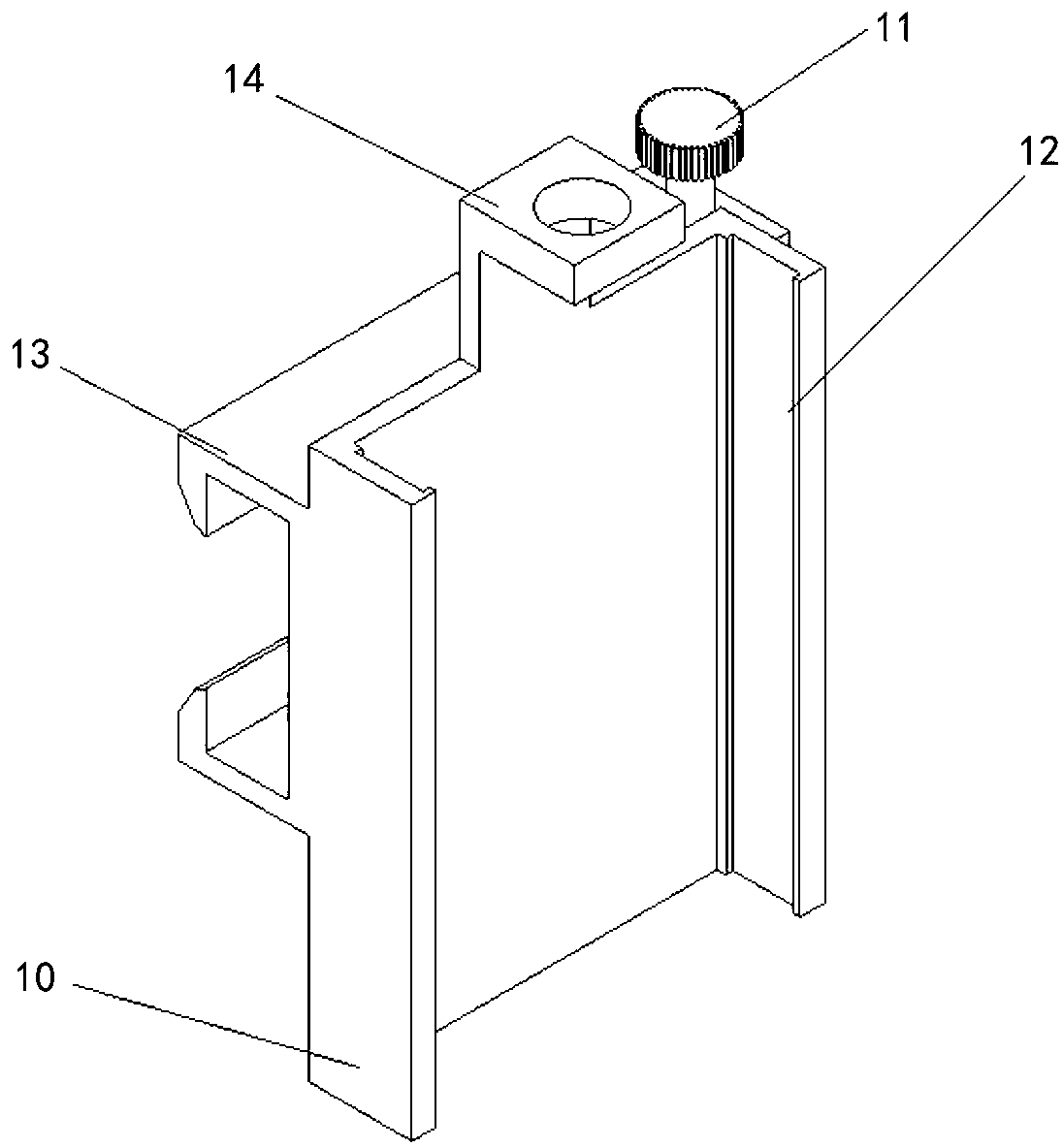
[0020] Such as figure 1 As shown, a clamp provided by the embodiment of the present invention includes a clamp base 10, a slider 20, a vertical adjustment assembly, a swing 40 and a clamping assembly. The vertical adjustment assembly is supported on the clamp base 10 in the vertical direction and is fixedly connected with the slide block 20 to adjust the relative position of the slide block 20 in the vertical direction with the clamp base 10; One end is rotatably connected to the slider 20, and the other end is installed with a clamping assembly.

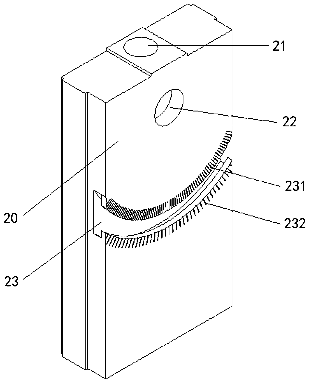
[0021] Specifically, combined with figure 2 As shown, the front side of the fixture base 10 has a vertical guide rail 12, and the slider 20 is installed in the guide rail 12 on the front side of the clamp base 10, and can be guided by the guide rail 12 along the vertic...


PUM


Abstract

The invention provides a clamp which comprises a clamp base body, a sliding block, a vertical adjustment assembly, a rotary pendulum and a clamping assembly. The vertical adjustment assembly is supported on the clamp base body along the vertical direction and fixedly connected with the sliding block so as to adjust the relative position of the sliding block in the vertical direction and the clamp base body. One end of the rotary pendulum is connected with the sliding block in a rotating mode, and the other end of the rotary pendulum is provided with the clamping assembly. The clamp can adjust angles, transverse coordinate positions and longitudinal coordinate positions of parts clamped on the clamp, and meanwhile, due to the fact that a movable clamping plate is detachable, multiple types of movable clamping plates in different shapes can be designed so as to achieve clamping for the various parts of different specifications or in different shapes. The clamp solves the problem that an existing clamp has no generality, can precisely control motions of the parts within a two-dimensional plane, and achieves the fact that the clamped parts can rotate at a certain angle and move transversely and longitudinally.

Description

technical field [0001] The invention relates to the technical field of machinery, in particular to a clamp. Background technique [0002] In the prior art, different parts to be processed have different dimensions and specifications, which impose strict requirements on the fixture used to install the parts. Therefore, the design of fixtures has the characteristics of specificity and fixity, and it is often necessary to design and manufacture corresponding fixtures according to the appearance characteristics of different parts and the characteristics of processing operations; this has caused a waste of materials. At the same time, the frequent replacement of fixtures during the processing of different parts also brings inconvenience to the operators, and increases the difficulty and complexity of the operations of the operators when processing the parts. Contents of the invention [0003] In view of this, it is necessary to provide a fixture for the problems existing in th...

Claims


Application Information

Patent Timeline
Patent Type & Authority Applications(China)
IPC IPC(8): B25B11/00
Inventor 张春雨李子夫陈贤帅
Owner 广东健齿生物科技有限公司
Why Eureka
Try Eureka