
Wrench

A wrench and finger technology, applied in the field of wrenches, can solve problems such as large action space, inability to proceed smoothly, unfavorable production, etc., and achieve the effects of improving work efficiency, improving safety, and realizing convenience.

Inactive Publication Date: 2015-11-11
赖玉春
View PDF5 Cites 1 Cited by
  • Summary
  • Abstract
  • Description
  • Claims
  • Application Information

AI Technical Summary

Problems solved by technology

With the help of a wrench to screw the nut, the wrench needs a large space for movement. For objects with limited space, it is not as convenient as screwing the bolt.
[0004] However, in the existing fixing method of screwing the bolt to realize the engagement of the bolt and the nut, the nut must be fixed before the bolt can be screwed.
In the prior art, although there are screw-driving tools that have been sleeved on the fingers, the fixing parts of this tool that are sleeved on the fingers all have a fixed size, and the fixing parts cannot be adjusted according to the thickness of the user's fingers. Due to the uneven thickness of the user's fingers, when different users perform the screwing operation, the fixing part cannot be placed on the finger because the fixing part is too small or the fixing part set on the finger is too loose. The operation cannot be carried out smoothly. This situation not only brings inconvenience to the user, but also causes the screw to loosen during use due to improper operation, which in turn causes equipment failure, which is not conducive to the progress of production.

Method used


Image

  • Wrench
  • Wrench
  • Wrench

Examples


Embodiment Construction

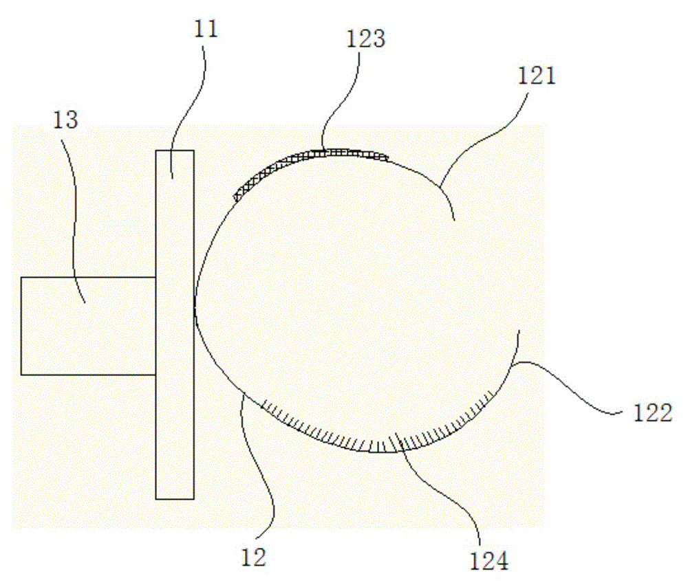
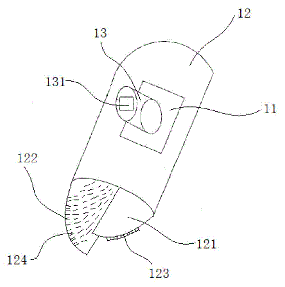
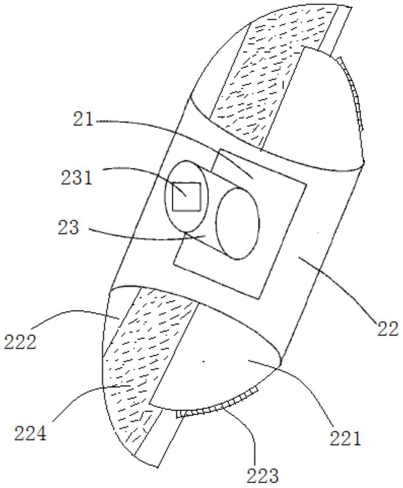
[0029] In order to make the above objects, features and advantages of the present invention more comprehensible, the present invention will be further described in detail below in conjunction with the accompanying drawings and specific embodiments.

[0030] Reference herein to "one embodiment" or "an embodiment" refers to a particular feature, structure or characteristic that can be included in at least one implementation of the present invention. "In one embodiment" appearing in different places in this specification does not all refer to the same embodiment, nor is it a separate or selective embodiment that is mutually exclusive with other embodiments.

[0031] see Figures 1A-1B As shown, it is a schematic structural view of the wrench of the present invention in the first embodiment. like Figures 1A-1B As shown, the wrench includes a fixed plate 11 , a flexible finger portion 12 and a positioning portion 13 . A flexible finger portion 12 is fixed on one side of the fixin...


PUM


Abstract

The invention provides a wrench which comprises a fixed plate, at least one flexible finger part and a positioning part, wherein the fixed plate adopts a square structure; each flexible finger part is fixed on one side of the fixed plate and comprises a first finger part and a second finger part; a first adhesive part is formed on the outer side of each first finger part; a second adhesive part is formed at a position, which corresponds to the first adhesive part, on the inner side of each second finger part; the second adhesive part is adhered to the first adhesive part, so that one flexible finger part is formed; the positioning part is fixed on the other side of the fixed plate. According to the wrench disclosed by the invention, the problem that the existing finger wrench is not universal can be solved; under the adhesion action of the first adhesive parts and the second adhesive parts of the flexible finger parts, a user can properly cover the fingers with the wrench to realize the convenience in operation, so that the working efficiency is improved; furthermore, a workpiece tightened by the wrench is unlikely to fall, and the production safety is improved.

Description

technical field [0001] The invention relates to the field of wrenches, in particular to a wrench that is put on a finger. Background technique [0002] Many objects in real life are fixedly connected to each other by screws. A screw lock connection usually consists of a threaded bolt on the surface and an internally threaded ring nut. When two objects are connected together by screws, the nut is usually placed on one side of the opening on the two objects, and the bolt is inserted into the opening from the other side of the opening on the two objects, and when it reaches the nut, the bolt is inserted into the opening. When threading, the bolt is screwed so that the thread of the bolt and the thread of the nut engage with each other to achieve fixation. Of course, the bolts can also be inserted into the openings of the two objects first, then the nuts can be placed on the bolts, and the nuts can be screwed to achieve the engagement of the bolts and the nuts. [0003] As me...

Claims


Application Information

Patent Timeline
Patent Type & Authority Applications(China)
IPC IPC(8): B25B13/48
CPCB25B13/481
Inventor 赖玉春
Owner 赖玉春
Learn More