Automobile, automobile seat and siding rail mechanism of automobile seat

A technology for car seats and slide rails, which is applied in the field of automobiles and car seats, can solve the problems of separation of moving slide rails from fixed slide rails, increase the production cost of slide rail mechanisms, and complex structure of anti-separation mechanisms, so as to ensure safety, Simple structure and enhanced rigidity effect

Inactive Publication Date: 2013-08-21
HUBEI AVIATION PRECISION MASCH TECH CO LTD
View PDF5 Cites 4 Cited by
  • Summary
  • Abstract
  • Description
  • Claims
  • Application Information

AI Technical Summary

Problems solved by technology

Obviously, the overall bearing capacity of the slide rail mechanism is enhanced through the above-mentioned anti-off mechanism, but the structure of the anti-off mechanism of this structure is complicated, which increases the manufacturing cost of the slide rail mechanism
In addition, the volume of the slide rail mechanism is increased, so there may be positional interference with other components on the car during assembly without changing the original design
[0006] In view of this, it is urgent to improve the structure of the slide rail mechanism of the existing car seat, and solve the problem of disengagement of the movable slide rail from the fixed slide rail without increasing the manufacturing cost.

Method used


Image

  • Automobile, automobile seat and siding rail mechanism of automobile seat
  • Automobile, automobile seat and siding rail mechanism of automobile seat
  • Automobile, automobile seat and siding rail mechanism of automobile seat

Examples


Embodiment Construction

[0029] The core of the present invention is to provide a slide rail mechanism for car seats. On the basis of controlling the manufacturing cost of the slide rail mechanism, it is not easy for the moving slide rail to move from the fixed slide rail under the alternating load or impact load of the safety belt. The purpose of detachment, so as to ensure the safety of the car during driving. On this basis, the present invention also provides a car seat including the above-mentioned slide rail mechanism, and a car including the above-mentioned car seat.

[0030] Without loss of generality, this embodiment will now be described in detail in conjunction with the accompanying drawings.

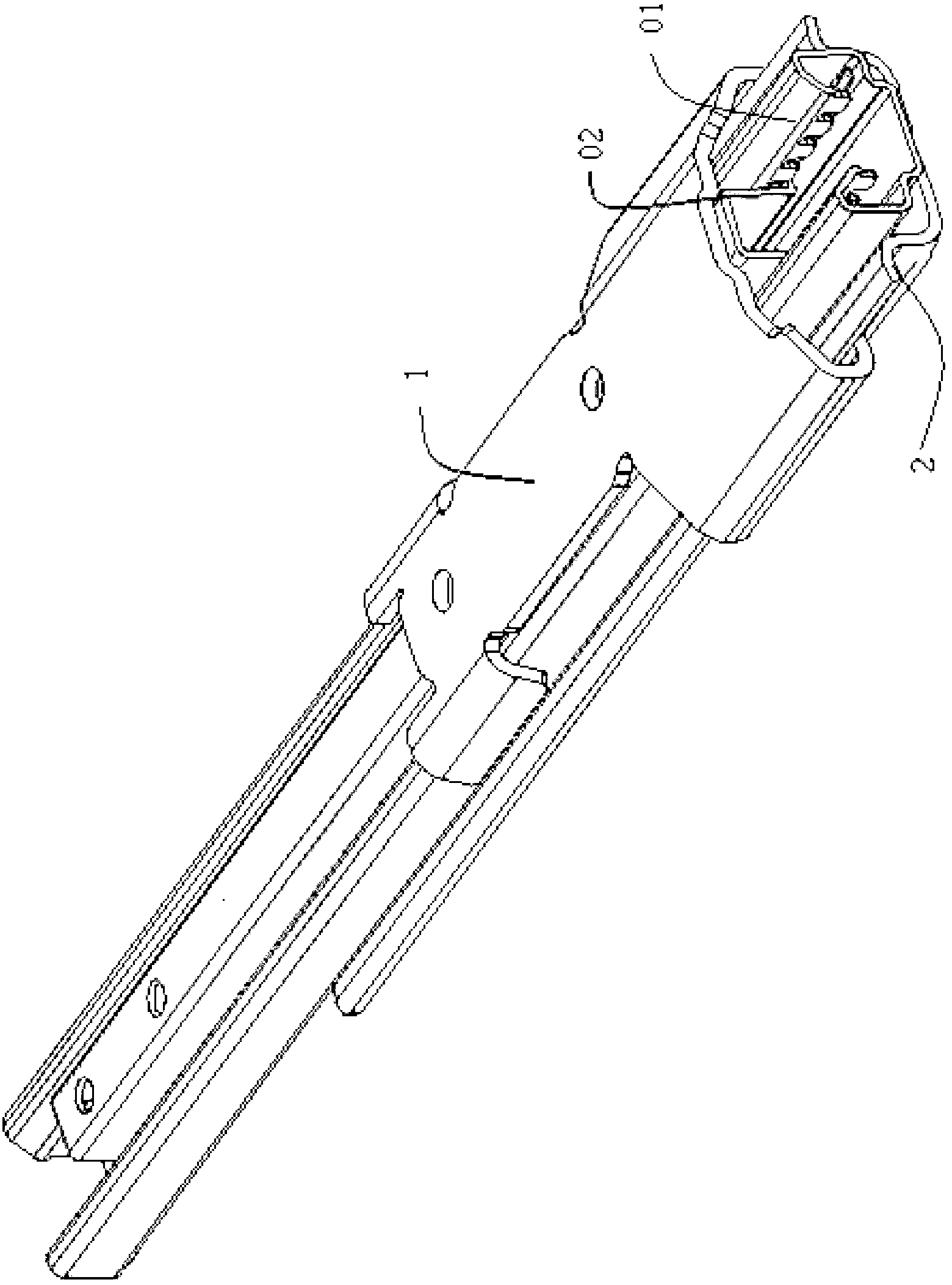
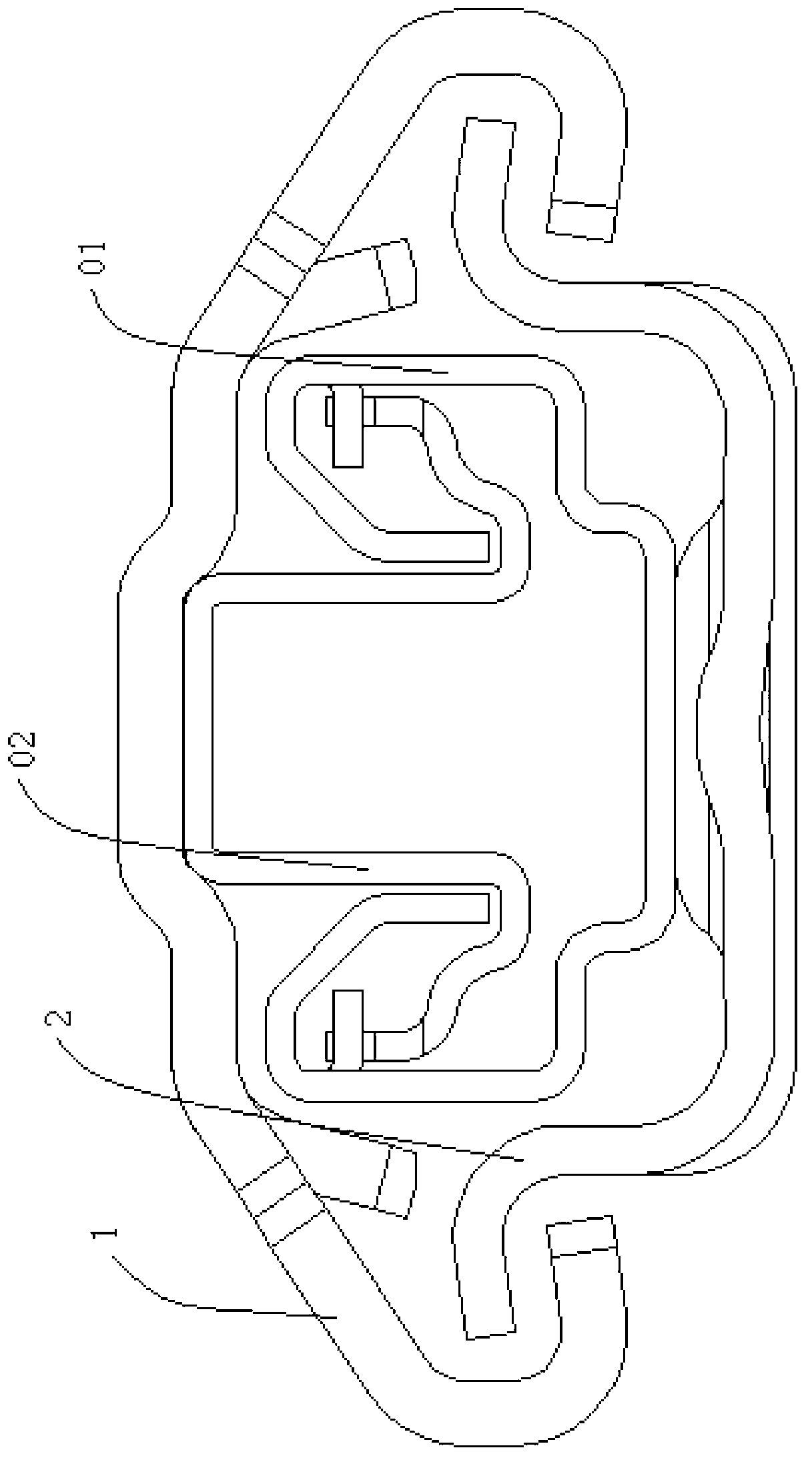
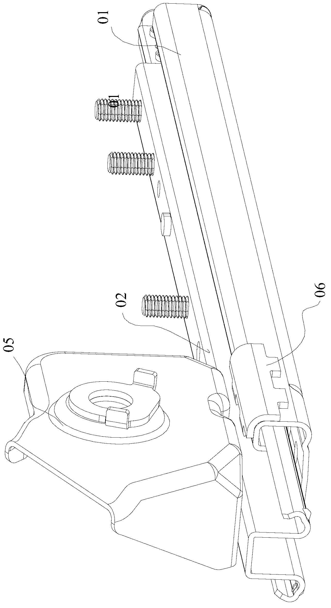
[0031] See Figure 4 , Figure 5 and Figure 6 ,in, Figure 4 It is an axonometric view of the first embodiment of the slide rail mechanism in the present invention, Figure 5 for Figure 4 Schematic diagram of the front view of the middle slide rail mechanism, Figure 6 for Figure 4 Schemati...


PUM


Abstract

The invention discloses a sliding rail mechanism used for an automobile seat. The sliding rail mechanism comprises a fixed sliding rail and a movable sliding rail, the fixed sliding rail comprises a U-shaped first connecting part and a first clamping part, the movable sliding rail comprises a U-shaped second connecting part and a second clamping part matched with the first clamping part, the fixed sliding rail and the movable sliding rail are clamped through the first clamping part and the second clamping part to form a cavity, a sliding component is arranged in the cavity, and the movable sliding rail can slide relative to the fixed sliding rail under the supporting of the sliding component. The sliding rail mechanism further comprises a reinforcing element arranged at the connecting position of the first connecting part and the first clamping part. Compared with the prior art, with the method that only the reinforcing element is arranged at the connecting position of the first connecting part and the first clamping part of the fixed sliding rail, rigidity in the area is enhanced, and therefore the problem that movable sliding rail departs from the fixed sliding rail is solved. On the basis, the invention further discloses the automobile seat comprising the sliding rail mechanism and an automobile comprising the automobile seats.

Description

technical field [0001] The invention relates to the field of vehicles, in particular to a slide rail mechanism for a car seat, a car seat including the slide rail mechanism, and a car including the car seat. Background technique [0002] In order to satisfy occupants of different sizes to have a comfortable seating space or for the driver to conveniently control the vehicle, the car seat is required to be adjustable in front and rear positions. The car seat slide rail is a device used to adjust the front and rear positions of the car seat. [0003] At present, the car seat generally includes a seat body and a slide rail mechanism, and the seat body is installed on the vehicle chassis through the slide rail mechanism; the slide rail mechanism usually includes a fixed slide rail fixed with the vehicle chassis and a Moving slide rail; a sliding fit is maintained between the moving slide rail and the fixed slide rail; in this way, through the slide rail mechanism, the seat body...

Claims


Application Information

Patent Timeline
IPC IPC(8): B60N2/07
Inventor 孙莹烽高元和黄克乐王景红
Owner HUBEI AVIATION PRECISION MASCH TECH CO LTD
Why Eureka
Try Eureka