Railway vehicle central suspension type self-height-adjusting bogie

A railway vehicle and suspension type technology, applied in the field of suspension type self-heightening bogies, can solve problems such as affecting the safety of vehicle operation, wear of wheels and rails, and easy breakage of couplers.

Active Publication Date: 2013-08-21
CRRC YANGTZE CO LTD
View PDF5 Cites 12 Cited by
  • Summary
  • Abstract
  • Description
  • Claims
  • Application Information

AI Technical Summary

Problems solved by technology

The three-piece bogie mainly uses the central bearing spring as the secondary suspension system. When the vehicle is running, the mass of the components below the secondary suspension system directly acts on the wheel rails without spring damping, so the distance between the wheel rails The vertical force of the truck is very large, which leads to the defects of such bogies as large unsprung mass, serious wheel and rail wear, and easy breakage of the coupler.
In this way, the action force between the wheel and rail cannot be effectively reduced when the vehicle is running with heavy loads, resulting in increased wear between the wheel and rail, shortening the service life of key components such as bolsters and side frames, and reducing the maintenance workload of the wheel and rail. and maintenance costs increased
At the same time, due to the coupler height difference between empty and heavy vehicles, the coupler is unevenly stressed, which is likely to cause coupler breakage accidents and affect the safety of vehicle operation.

Method used


Image

  • Railway vehicle central suspension type self-height-adjusting bogie
  • Railway vehicle central suspension type self-height-adjusting bogie
  • Railway vehicle central suspension type self-height-adjusting bogie

Examples


Embodiment Construction

[0040] Below in conjunction with accompanying drawing and specific embodiment the present invention is described in further detail:

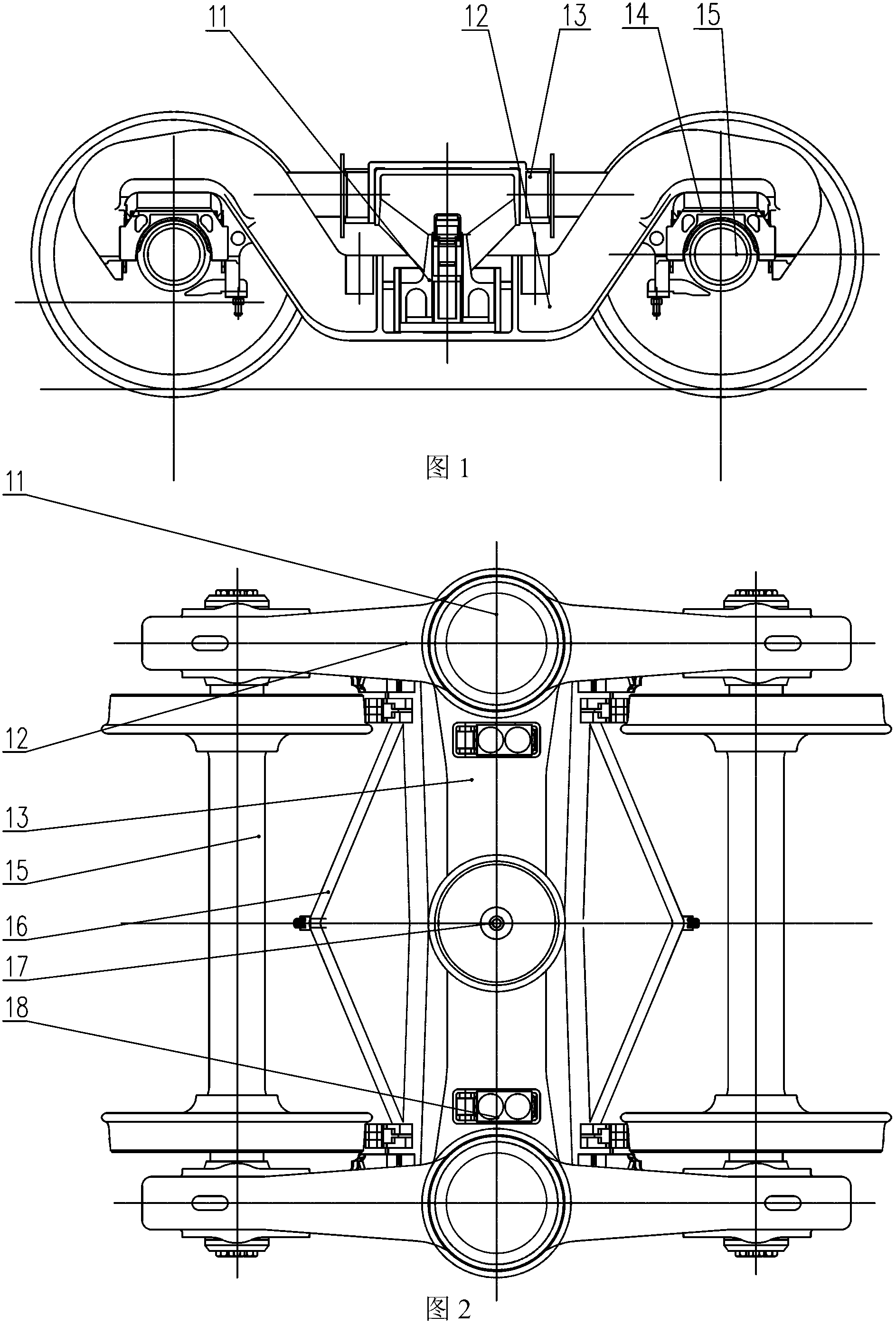
[0041] Such as Figure 1~2 The centrally suspended self-heightening bogie of a railway vehicle as shown includes a wheel axle composition 15, a side frame composition 12, a bolster 13, and a corresponding foundation braking device 16, and the pedestals at both ends of the side frame composition 12 are suspended through the axle boxes The device 14 is placed on the axle assembly 15, and the upper center and both sides of the bolster 13 are respectively provided with a lower center plate 17 and a lower side bearing 18, and the two ends of the bolster 13 and the central frame of the side frame assembly 12 are provided with The spring deflection automatic adjustment device 11, the spring deflection automatic adjustment device 11 can choose a variety of structural forms, two types are introduced in detail below.

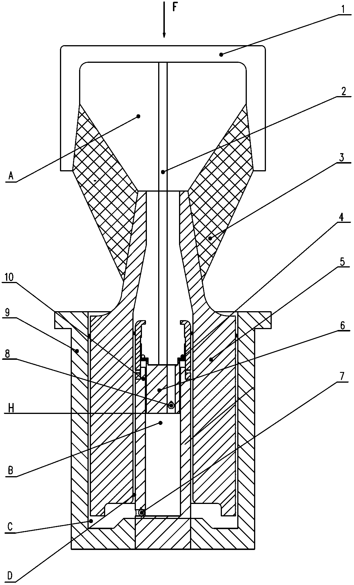
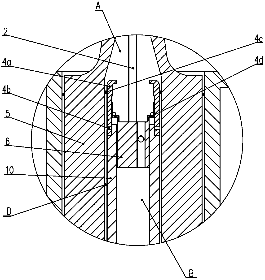
[0042] Such as Figure 3~6 The fir...


PUM


Abstract

The invention discloses a railway vehicle central suspension type self-height-adjusting bogie. A spring deflection automatic adjusting device is arranged in the middle of a central square frame formed by two ends of a swing bolster of the bogie and a side frame. The device is mainly composed of an inner cylinder body, an outer cylinder body, an inner piston, an outer piston, a push-pull rod, a rubber bearing spring and a bearing top cover. Four hydraulic oil cavities enclose the device. A first one-way valve controlling break-make of a first hydraulic oil cavity and a second hydraulic oil cavity is arranged in an axial through hole of the inner piston. A second one-way valve controlling break-make of the second hydraulic oil cavity and a third hydraulic oil cavity is arranged in a through hole in the side wall of the bottom of the inner cylinder body. A circuit switch device controlling break-make of the first hydraulic oil cavity and a fourth hydraulic oil cavity is arranged at the top of the inner cylinder body. The fourth hydraulic oil cavity is directly communicated with the third hydraulic oil cavity. Through the dynamic balance function of the device in the vehicle body motion vibration process, the height difference between an empty vehicle and a heavy vehicle can be eliminated, working deflection of the bearing spring can be increased, and low power performance between wheel tracks can be improved to a maximum degree. The railway vehicle central suspension type self-height-adjusting bogie is especially suitable for bogies with big axle loads.

Description

technical field [0001] The invention relates to a railway vehicle bogie, in particular to a centrally suspended self-heightening bogie for a railway vehicle. Background technique [0002] Railway vehicles operate by traction and braking adhesive friction generated by the interaction between the wheels on the bogie and the railway track. As the load of railway vehicles increases, the axle load of the vehicles also increases correspondingly, which will inevitably lead to an increase in the force between the wheels and rails, thereby accelerating the wear of the wheels and rails. Practical experience shows that when the vehicle axle load increases, the wheel-rail contact stress increases, and the longitudinal and lateral friction of the wheel tread and the side pressure of the wheel and rail increase accordingly, resulting in vertical wear, side wear and plastic flow of the rail. Increase, the wear of the wheel rim and tread also increases accordingly. [0003] In order to re...

Claims


Application Information

Patent Timeline
Patent Type & Authority Applications(China)
IPC IPC(8): B61F5/16B61F5/08
Inventor 曹阳姜瑞金徐勇李燕慧易军恩
Owner CRRC YANGTZE CO LTD
Why Eureka
Try Eureka