Wire feeding device of sewing machine

A thread feeding device and sewing machine technology, applied in the direction of sewing machine metering device, sewing machine components, sewing equipment, etc., can solve the problems of poor thread tightness, trouble, thread breakage, etc., and achieve the effect of simplifying cumbersome operations

Active Publication Date: 2013-08-21
株式会社飞马
View PDF10 Cites 0 Cited by
  • Summary
  • Abstract
  • Description
  • Claims
  • Application Information

AI Technical Summary

Problems solved by technology

[0005] However, in the thread feeding device 9 of the above-mentioned sewing machine, when switching between harder stitches and softer stitches, it is necessary to reselect the first thread feeding hole 3 or the second thread feeding hole 3 that is integrally located at the swinging thread take-up member 6. Thread feed hole 4 and re-passing the suture through either of

Method used


Image

  • Wire feeding device of sewing machine
  • Wire feeding device of sewing machine
  • Wire feeding device of sewing machine

Examples


Embodiment Construction

[0025] Next, preferred embodiments of the thread feeding device of the sewing machine according to the present invention will be described based on the drawings.

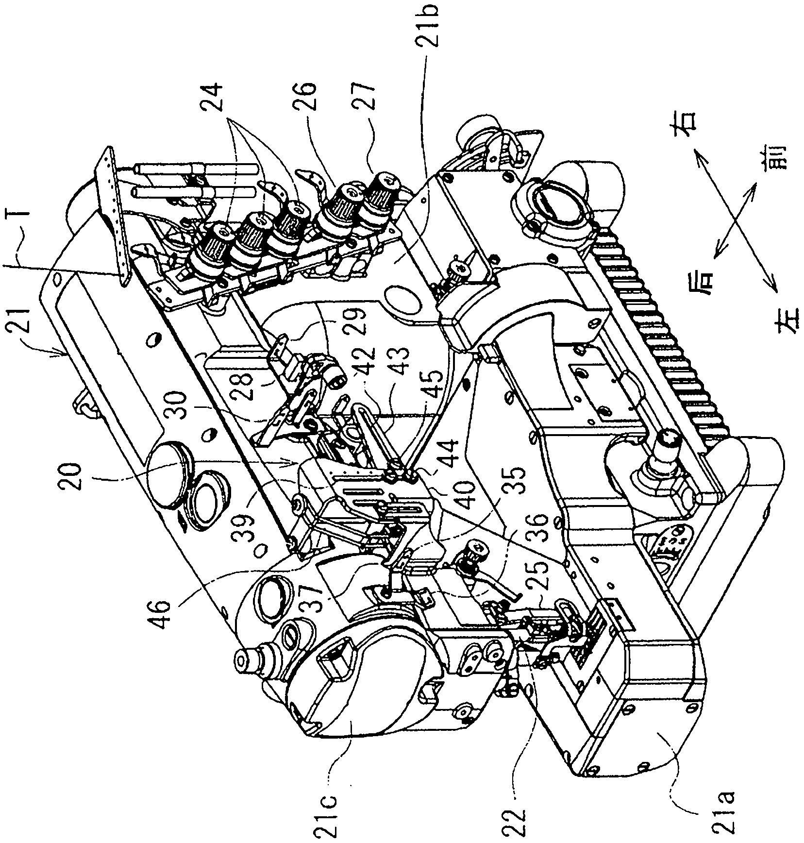
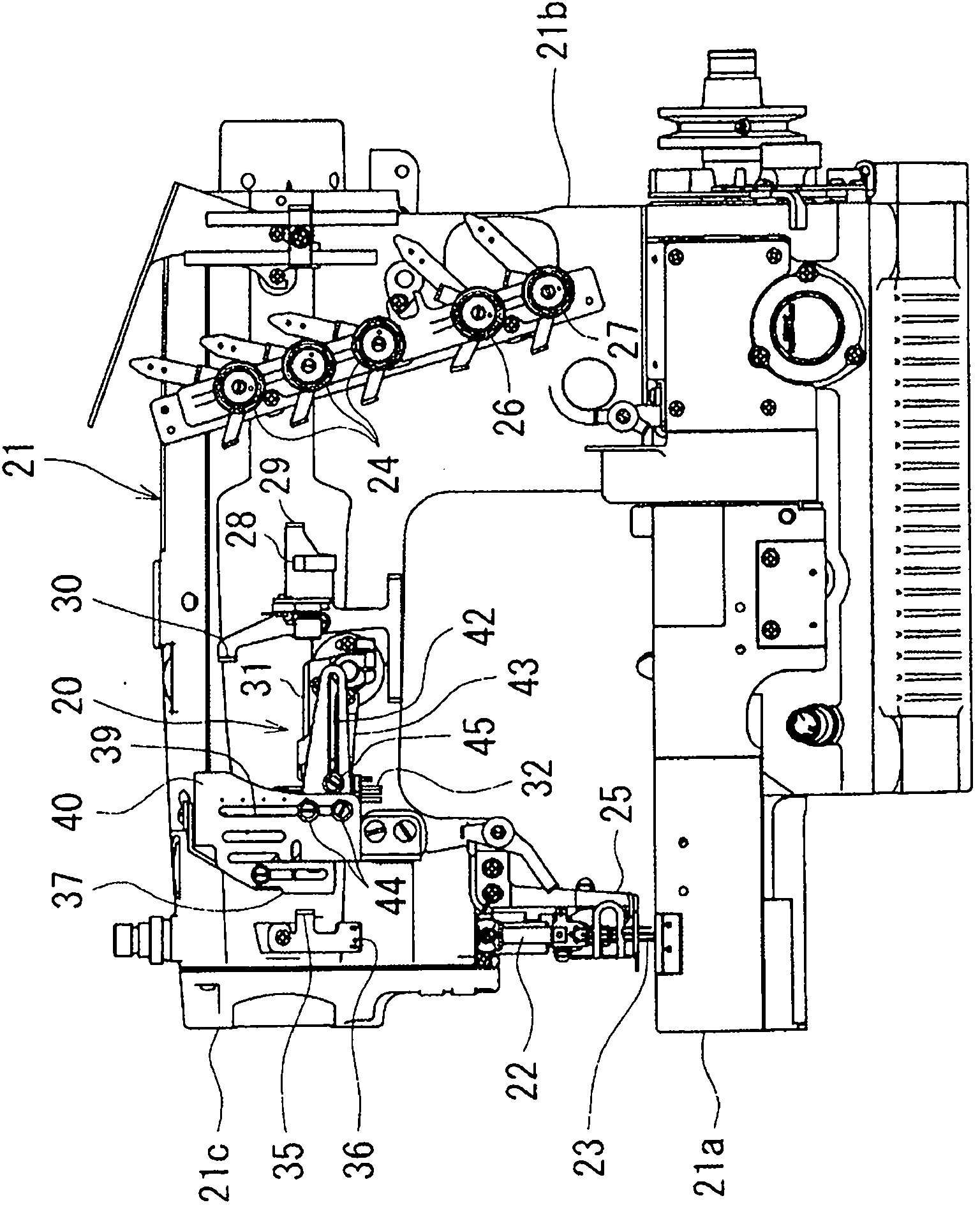
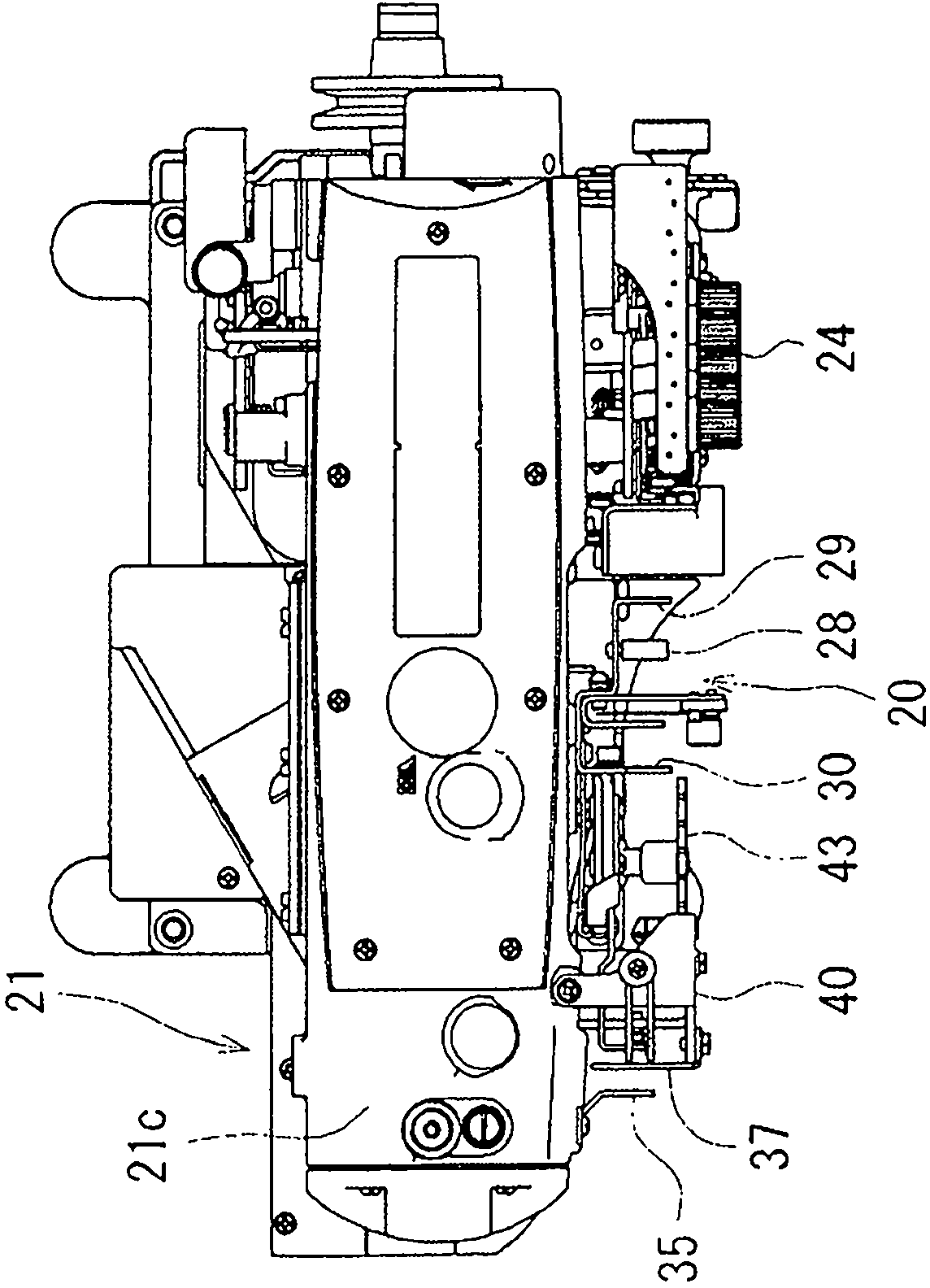
[0026] Figure 1~Figure 3 A sewing machine 21 as a double-thread lockstitch sewing machine having a thread feeding device 20 as an example of an embodiment of the present invention is shown. exist Figure 1~Figure 3 Among them, the sewing machine 21 has a base portion 21a, a vertical body portion 21b erected from the base portion 21a, and a sewing machine arm portion 21c extending from the vertical body portion 21b parallel to the base portion 21a.

[0027] Sewing machine 21 comprises: three thread grippers 24, and they are used for respectively applying prescribed tension to the suture passing through each needle 23 in the three needles 23 fixed on the lower end of needle bar 22, and needle bar 22 is formed by The main shaft of the sewing machine, not shown, is reciprocatingly driven up and down; the thread clamp...


PUM


Abstract

The invention provides a wire feeding device of a sewing machine, which can simplify tedious operations of wearing sewing wires again during switching a hard stitch with a soft stitch. The wire feeding device (20) of the sewing machine (21) has a wire stirring and picking part (31), a first wire guide part (29), a second wire guide part (30) and a movable wire guide member (32). The wire stirring and picking part (31) having a wire feeding hole (34) at a swing front end side is arranged in a way that the wire stirring and picking part (31) can vertically swing surrounding a swing shaft (31a) which supports a swing base end side. The movable wire guide member (32) is formed independent of the wire stirring and picking part (31) and is arranged between the wire feeding hole (34) and the second wire guide part (30) to adjust positions vertically and horizontally.

Description

technical field [0001] The present invention relates to a thread feeding (Japanese: 系缲り) device of a sewing machine for facilitating picking out a thread to a sewing needle. Background technique [0002] In the past, as the thread feeding device of this sewing machine, for example, there are Figure 11 The thread feeding device 9 of the sewing machine 8 constituted as shown (for example, refer to Patent Document 1), it includes: a movable thread guide 1; The first thread-feeding hole 3 and the second thread-feeding hole 4 for sutures to pass through, and center on one end side to reciprocate and swing synchronously with the up and down movement of the needle bar 5 to control the amount of thread picking out; the needle bar thread take-up The part 7, which is fixed on the upper end of the needle bar 5, has a thread feeding hole 7a through which the suture can pass, and controls the amount of the suture to be pulled out. Wherein, the thread feeding device 9 of the sewing mach...

Claims


Application Information

Patent Timeline
IPC IPC(8): D05B45/00
Inventor 宫武昌夫久原俊雄南云由纪子
Owner 株式会社飞马
Why Eureka
Try Eureka