disk device

A technology of guiding part and inserting port, which is applied in the direction of record information storage and instrumentation, and can solve problems such as poor disk delivery and easy collision of disks

Active Publication Date: 2017-03-01
ALPINE ELECTRONICS INC
View PDF5 Cites 0 Cited by
  • Summary
  • Abstract
  • Description
  • Claims
  • Application Information

AI Technical Summary

Problems solved by technology

When the above-mentioned mechanism disposing part is placed too close to the conveying area or the above-mentioned mechanism disposing part is arranged at a position overlapping with the conveying area in order to constitute a compact housing, and when the disc that has been unfastened by the rotary driving part is sent out from the insertion port, The disc is likely to collide with the above-mentioned mechanism, and the disc feeding failure is likely to occur

Method used


Image

  • disk device
  • disk device
  • disk device

Examples


Embodiment Construction

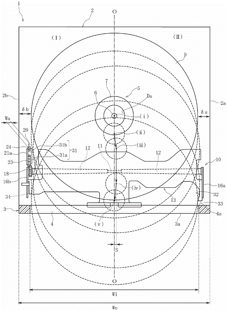
[0047] figure 1 The shown disk device 1 has a metal casing 2 and a synthetic resin panel 3 provided in front of the casing 2. On the panel 3, along the figure 1 There is an insertion port 4 in the shape of an elongated slit in the left-right direction opening. The casing of the disk device 1 is constituted by the housing 2 and the panel 3 .

[0048] The panel device 1 is for a vehicle, and the housing 2 is embedded in an instrument panel or instrument panel in a vehicle cabin, and is provided so that the panel 3 is exposed on the surface.

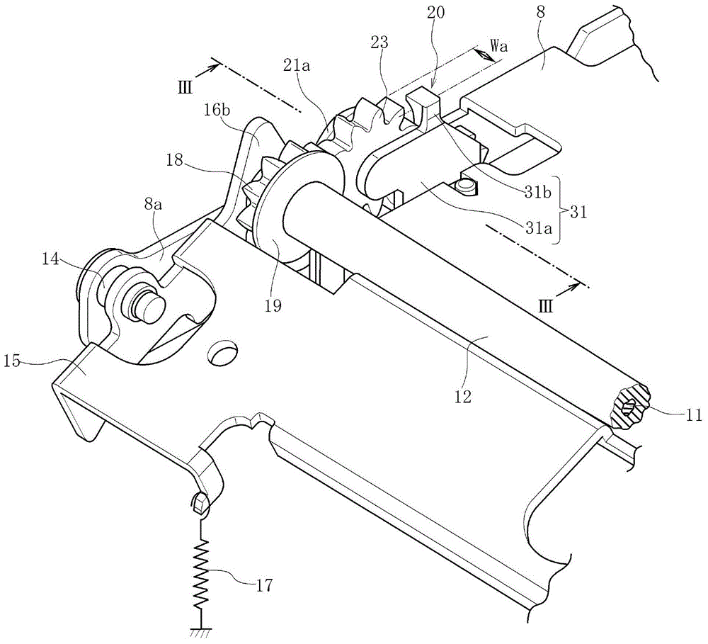
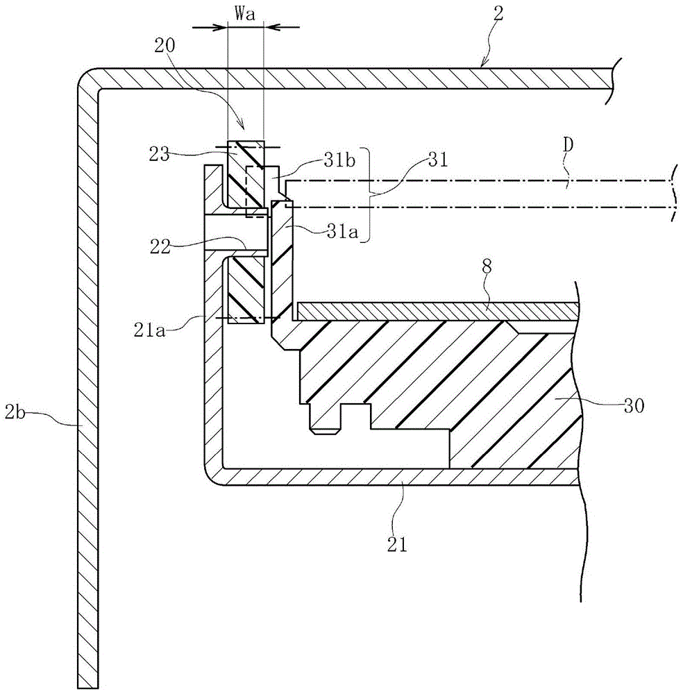
[0049] Inside the frame 2 there are figure 2 The mechanism base 8 is shown. The mechanism base 8 is supported by elastic members such as oil dampers and tension coil springs inside the frame body 2 . Such as figure 1 As shown, a rotation drive unit 5 is provided inside the frame body 2 . The rotary drive unit 5 includes a rotary shaft 6 , a turntable 7 fixed to the rotary shaft 6 , a spindle motor for rotating the rotary shaft 6 , an...


PUM

PropertyMeasurementUnit
diameteraaaaaaaaaa

Abstract

The invention provides a disc device which can shorten the width of a housing and can send out a disk (D) successfully even though a mechanism configuration part is closing to a disk conveying area for configuration. The width (W0) of a frame (2) which forms the disk device (1) is shortened, the mechanism configuration part (20) is configured at a position close to or repeated to the disk conveying area. The disk (D) sent out collides with a first guiding part (31) and then move right, and thus the disk (D) can be sent out without colliding with transmission gears (23, 24) of the mechanism configuration part (20). Then, the disk (D) is pressed left by a second guiding part (33), and the center of the disk returns to a position on a conveying reference line (O), and the disk is sent out from an insertion opening (4).

Description

technical field [0001] The present invention relates to a disk device in which a disk is inserted through a slit-shaped insertion opening formed in a housing, and more particularly to a disk device capable of efficiently using the space inside the housing and smoothly ejecting the disk. Background technique [0002] The disk drive described in Patent Document 1 employs a so-called suction method, in which a disk is inserted in a direction along the disk surface through a slit-shaped insertion opening opened at the front of the case. In this disc device, a transport mechanism including transport rollers is provided inside the housing, and the disc inserted from the insertion port is fed into the housing by the rotational force of the transport rollers. A rotary drive unit is provided in the housing, and the center hole of the loaded disc is provided and held on a turn table of the rotary drive unit. [0003] The disc held by the rotary drive unit can be rotated together with...

Claims


Application Information

Patent Timeline
Patent Type & Authority Patents(China)
IPC IPC(8): G11B17/051
Inventor 川濑裕志
Owner ALPINE ELECTRONICS INC
Why Eureka
Try Eureka