Broadband antenna

A wide-band antenna and wireless signal technology, applied to the antenna, the device that enables the antenna to work in different bands at the same time, the structural form of the radiation element, etc., can solve the problems that cannot meet the needs of users, and achieve the effect of the best voltage standing wave ratio

Active Publication Date: 2013-08-21
WISTRON NEWEB
View PDF6 Cites 16 Cited by
  • Summary
  • Abstract
  • Description
  • Claims
  • Application Information

AI Technical Summary

Problems solved by technology

However, with the evolution of wireless communication technology, the operating frequency of wireless communication systems is getting wider and wider, and the multi-frequency antenna 1 in the prior art can no longer meet the needs of users.

Method used


Image

  • Broadband antenna
  • Broadband antenna
  • Broadband antenna

Examples


Embodiment Construction

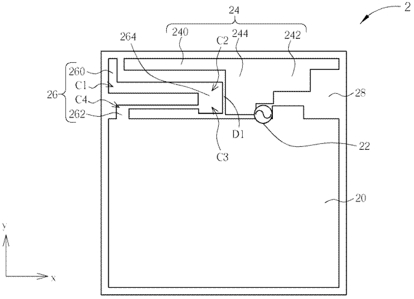
[0045] Please refer to figure 2 , figure 2 It is a schematic diagram of a broadband antenna 2 of the present invention. Such as figure 2 As shown, the broadband antenna 2 is located on an XY plane, which includes an X-axis direction and a Y-axis direction and the two are perpendicular to each other, and the broadband antenna 2 is carried by a substrate 28, and includes a grounding element 20, a feeder The input source 22 , a first radiator 24 and a second radiator 26 . The first radiator 24 is used to transmit a high-frequency band, and its total length is roughly equal to a quarter wavelength of the high-frequency wireless signal, and the first radiator 24 further includes a first radiator 240 and a second radiator 242 And a conducting element 244, wherein the first radiating element 240 and the second radiating element 242 both extend along the X-axis direction, and the conducting element 244 connects the first radiating element 240 and the second radiating element 242...


PUM


Abstract

A broadband antenna comprises a grounding component electrically connected to one grounding end, a feed-in source used for receiving a wireless signal, a first radiating body, a second radiating part, a conductive component, a second radiating body and a third radiating part, wherein the first radiating body comprises a first radiating part extending in the first direction, the second radiating part is extended in the opposite direction of the first direction, the conductive component is extended in the second direction, the second radiating body comprises a short circuit component electrically connected with the grounding component, the third radiating part comprises a subsection which keeps a first distance with the conductive component, and the first distance makes the third radiating part and the conductive component generate a coupling connecting effect, wherein the average perpendicular distance from the second radiating body to the grounding component is smaller than that from the first radiating part to the grounding component.

Description

technical field [0001] The invention refers to a broadband antenna, especially a broadband antenna utilizing the vertical coupling connection effect. Background technique [0002] Electronic products with wireless communication functions, such as notebook computers, personal digital assistants (PDA), etc., transmit or receive radio waves through antennas to transmit or exchange radio signals, and then access wireless networks. Therefore, in order to allow users to access wireless communication networks more conveniently, the bandwidth of an ideal antenna should be increased as much as possible within the allowable range, while the size should be reduced as much as possible to match the trend of shrinking electronic products. [0003] In the prior art, such as China Taiwan Patent No. I318022, a multi-frequency antenna 10 for wireless transmission has been disclosed, such as figure 1 shown. The multi-frequency antenna 10 includes a grounding part 100, a first radiating part ...

Claims


Application Information

Patent Timeline
Patent Type & Authority Applications(China)
IPC IPC(8): H01Q1/36H01Q5/00H01Q5/50
Inventor 黄国仑江毓彧曾上晋
Owner WISTRON NEWEB
Why Eureka
Try Eureka