Indoor dry powder intelligent fire extinguishing system

A fire-extinguishing system and dry powder technology, applied in the field of fire-extinguishing systems, can solve problems such as inability to spray water, inability to extinguish flames, and limited fire-extinguishing effect.

Active Publication Date: 2013-08-28
DALIAN ZHIHUIDA TECH CO LTD
View PDF9 Cites 12 Cited by
  • Summary
  • Abstract
  • Description
  • Claims
  • Application Information

AI Technical Summary

Problems solved by technology

However, the disadvantages of the traditional indoor fire extinguishing system are: firstly, it cannot spray water in a targeted manner, and can only spray water in a large area indoors, and the fire extinguishing effect is very limited; secondly, it encounters oil fires, electric fires, etc. fire source, the water spray method not only cannot extinguish the flame, but will cause a larger and more serious disaster, and its application range is also very limited
[0003] In addition to the above-mentioned automatic fire extinguishing system, dry powder fire extinguishers are often installed indoors as a spare equipment for fire extinguishing. However, on the one hand, dry powder fire extinguishers have the problem of unskilled operation, and the more important thing is that after the dry powder inside is mixed with high-pressure nitrogen, it will Chemical reaction, so there is a certain period of validity. After the validity period, the dry powder fire extinguisher loses its fire extinguishing function and needs to be replaced. This not only increases the cost, but more importantly, if you forget to replace the inner vessel on time, it may not be able to Fire extinguishing, resulting in greater loss of personnel and property

Method used


Image

  • Indoor dry powder intelligent fire extinguishing system
  • Indoor dry powder intelligent fire extinguishing system
  • Indoor dry powder intelligent fire extinguishing system

Examples


Embodiment Construction

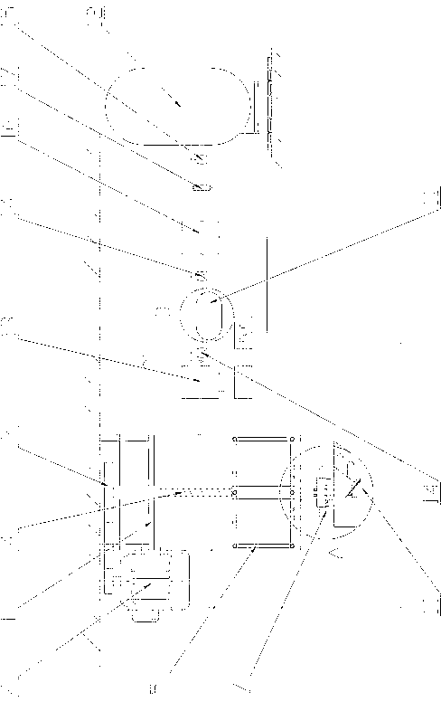
[0019] The specific implementation manner of the present invention will be described below with reference to the accompanying drawings. Such as figure 1 , figure 2 , image 3 , Figure 4 Shown: an indoor dry powder intelligent fire extinguishing system, the fire extinguishing system includes a fixed frame 1, the fixed frame 1 is set at a high place indoors (such as in the ceiling), and a lifting motor 2 is arranged on the fixed frame 1, the The output end of the lifting motor 2 is connected with the lifting gear 3 through the gear transmission pair, and the lifting gear 3 can rotate coaxially with the lifting screw 4. The lifting screw 4 is covered with a lifting frame 5 matching its thread. The lower end is provided with a turntable 7, which is controlled by a rotating motor 6. On the turntable 7, an infrared thermometer 8, an infrared range finder 9 and a telescopic nozzle 10 are arranged, wherein the telescopic nozzle 10 passes through the pipeline and the dry powder co...


PUM


Abstract

The invention discloses an indoor dry powder intelligent fire extinguishing system which comprises a fixed frame, wherein the fixed frame is fixedly arranged indoors; a lifting motor is arranged on the fixed frame, and the output end of the lifting motor is connected with a lifting gear by a gear transmission pair; the lifting gear is connected with a lifting screw rod which is supported in the fixed frame by a bearing; a lifting frame which is matched with threads of the lifting screw rod is sheathed on the lifting screw rod, and a rotary disc which is controlled by a rotary motor is arranged on the lower end of the lifting frame; an infrared thermometer, an infrared distancer and a telescopic nozzle are arranged on the rotary disc, wherein the telescopic nozzle is communicated with a dry powder container through a pipeline, and the dry powder container is communicated with a high-pressure nitrogen storage tank; a first electromagnetic valve which is controlled by a PLC (Programmable Logic Controller) is arranged between the telescopic nozzle and the dry powder container; and the lifting motor, the rotary motor, the infrared thermometer, the infrared distancer, the telescopic nozzle and the first electromagnetic valve are uniformly controlled by the PLC.

Description

technical field [0001] The invention relates to a fire extinguishing system, in particular to an indoor dry powder intelligent fire extinguishing system. Background technique [0002] The indoor fire extinguishing system is a fire prevention facility, which can detect whether there is an open fire in the room, and spray water into the room to realize the fire extinguishing function. However, the disadvantages of the traditional indoor fire extinguishing system are: firstly, it cannot spray water in a targeted manner, and can only spray water in a large area indoors, and the fire extinguishing effect is very limited; secondly, it encounters oil fires, electric fires, etc. fire source, the water sprinkler method not only cannot extinguish the flame, but will cause a larger and more serious disaster, and its application range is also very limited. [0003] In addition to the above-mentioned automatic fire extinguishing system, dry powder fire extinguishers are often installed ...

Claims


Application Information

Patent Timeline
Patent Type & Authority Applications(China)
IPC IPC(8): A62C35/15A62C37/00
Inventor 林泉
Owner DALIAN ZHIHUIDA TECH CO LTD
Why Eureka
Try Eureka