Automatic fire extinguishing system for server

An automatic fire extinguishing system and server technology, applied in the server field, can solve the problems of personnel, property loss, time difference, passive management and low efficiency of operation and maintenance, etc., and achieve the effect of improving timeliness and accuracy.

Active Publication Date: 2019-11-15
INSPUR SUZHOU INTELLIGENT TECH CO LTD
View PDF5 Cites 2 Cited by
  • Summary
  • Abstract
  • Description
  • Claims
  • Application Information

AI Technical Summary

Problems solved by technology

[0002] The server is exposed to various environmental stresses during the product life cycle, including changes in temperature, humidity, voltage, and current. The accumulation of stress exceeds the rated range that parts and boards can withstand, resulting in high temperature and fire; the existing early warning mechanism is mostly monitored by using temperature sensors, which are read by BMC (Baseboard Management Controller) on the PCB board. The temperature sensing circuit on the computer and the built-in temperature value of the IC chip are used for calculation. When the temperature exceeds the set threshold, an alarm will be generated to notify the IT personnel. After receiving the alarm, the IT personnel will go to the scene to eliminate it. However, there is a time gap between the discovery of the alarm and the arrival of the IT personnel at the scene, which makes this kind of passive management have the problem of low operation and maintenance efficiency; in addition, today's large server data centers generally adopt an unattended mode, when the server fails When the system catches fire, if the maintenance personnel cannot rush to the scene in time, it will cause huge loss of personnel and property

Method used


Image

  • Automatic fire extinguishing system for server
  • Automatic fire extinguishing system for server
  • Automatic fire extinguishing system for server

Examples


Embodiment Construction

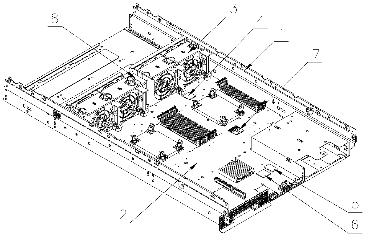
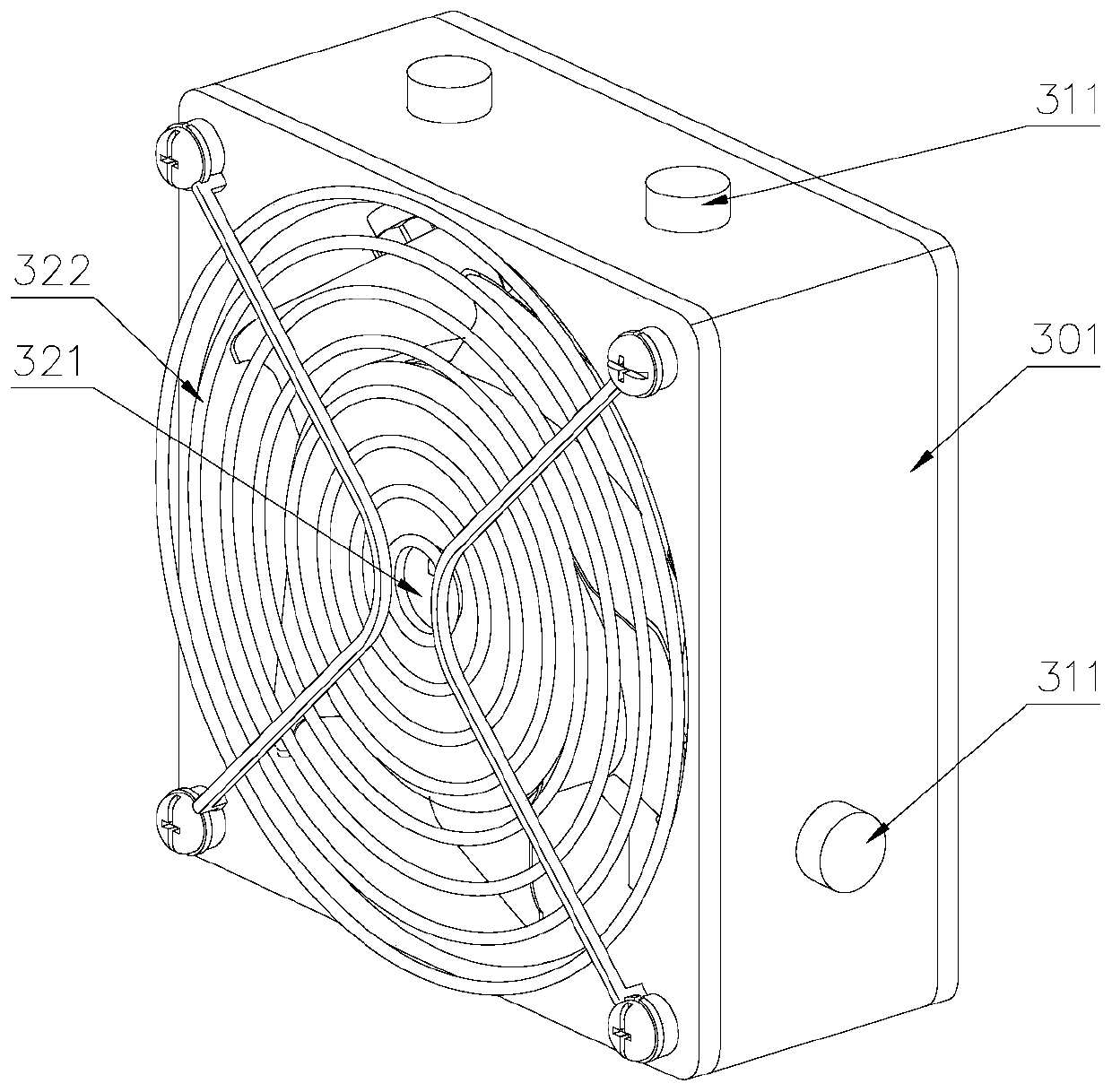
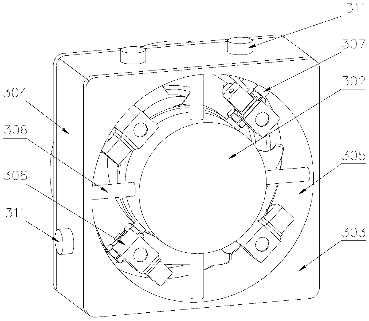
[0033] Attached below Figure 1-8 , clearly and completely describe the technical solutions in the embodiments of the present invention, obviously, the described embodiments are only some of the embodiments of the present invention, not all of them. Based on the embodiments of the present invention, all other embodiments obtained by persons of ordinary skill in the art without making creative efforts belong to the protection scope of the present invention.

[0034] In describing the present invention, it should be understood that the terms "longitudinal", "transverse", "upper", "lower", "front", "rear", "left", "right", "vertical", The orientations or positional relationships indicated by "horizontal", "top", "bottom", "inner", "outer", etc. are based on the orientations or positional relationships shown in the drawings, and are only for the convenience of describing the present invention, rather than indicating or It should not be construed as limiting the invention by imply...


PUM


Abstract

The invention discloses an automatic fire extinguishing system for a server. A PCB is provided with a smoke sensor, a fan module comprises a plurality of groups of fans, a plurality of storage tanks are formed in a closed space defined by a shell, an enclosure and an inner ring, and a fire extinguishing material is arranged in the storage tanks; a blowing opening is formed in one side of a rotating disc, a blowing pipe is arranged outside the rotating shaft in a sleeving mode, a plurality of communicating pipes are connected to the blowing pipe in a penetrating mode, and the other ends of thecommunicating pipes are communicated with the storage tanks. According to the automatic fire extinguishing system, the smoke sensor is arranged at an air outlet of the case, the fire extinguishing material is in the storage tanks, when the smoke sensor detects that smoke in the system is generated, the signal is transmitted to the BMC, the BMC controls the electromagnetic valve on the communicating pipe to be opened after receiving the smoke sensor signal, the fire extinguishing material is dispersed inside the system under the action of the air flow through the blowing opening, the fire extinguishing requirement is met, further spreading of fire is avoided, and further loss of personnel and property is avoided.

Description

technical field [0001] The invention belongs to the technical field of servers, in particular to an automatic fire extinguishing system for servers. Background technique [0002] The server is exposed to various environmental stresses during the product life cycle, including changes in temperature, humidity, voltage, and current. The accumulation of stress exceeds the rated range that parts and boards can withstand, resulting in high temperature and fire; the existing early warning mechanism is mostly monitored by using temperature sensors, which are read by BMC (Baseboard Management Controller) on the PCB board. The temperature sensing circuit on the computer and the built-in temperature value of the IC chip are used for calculation. When the temperature exceeds the set threshold, an alarm will be generated to notify the IT personnel. After receiving the alarm, the IT personnel will go to the scene to eliminate it. However, there is a time gap between the discovery of the ...

Claims


Application Information

Patent Timeline
Patent Type & Authority Applications(China)
IPC IPC(8): A62C3/16A62C37/00
CPCA62C3/16A62C37/04
Inventor 刘建良
Owner INSPUR SUZHOU INTELLIGENT TECH CO LTD
Why Eureka
Try Eureka