Optical bonding member and touch display device

A technology for touch devices and display devices, applied in the direction of adhesives, film/sheet-like adhesives, etc., can solve the problems of rising production costs and increasing steps, avoiding specular reflection, reducing refraction and scattering, and avoiding cumbersome processes. Effect

Active Publication Date: 2013-08-28
SHANGHAI AVIC OPTOELECTRONICS
View PDF4 Cites 1 Cited by
  • Summary
  • Abstract
  • Description
  • Claims
  • Application Information

AI Technical Summary

Problems solved by technology

However, the above-mentioned touch display device 200 increases the production cost due to the addition of the coating and curing process of the liquid optic

Method used


Image

  • Optical bonding member and touch display device
  • Optical bonding member and touch display device
  • Optical bonding member and touch display device

Examples


Embodiment 1

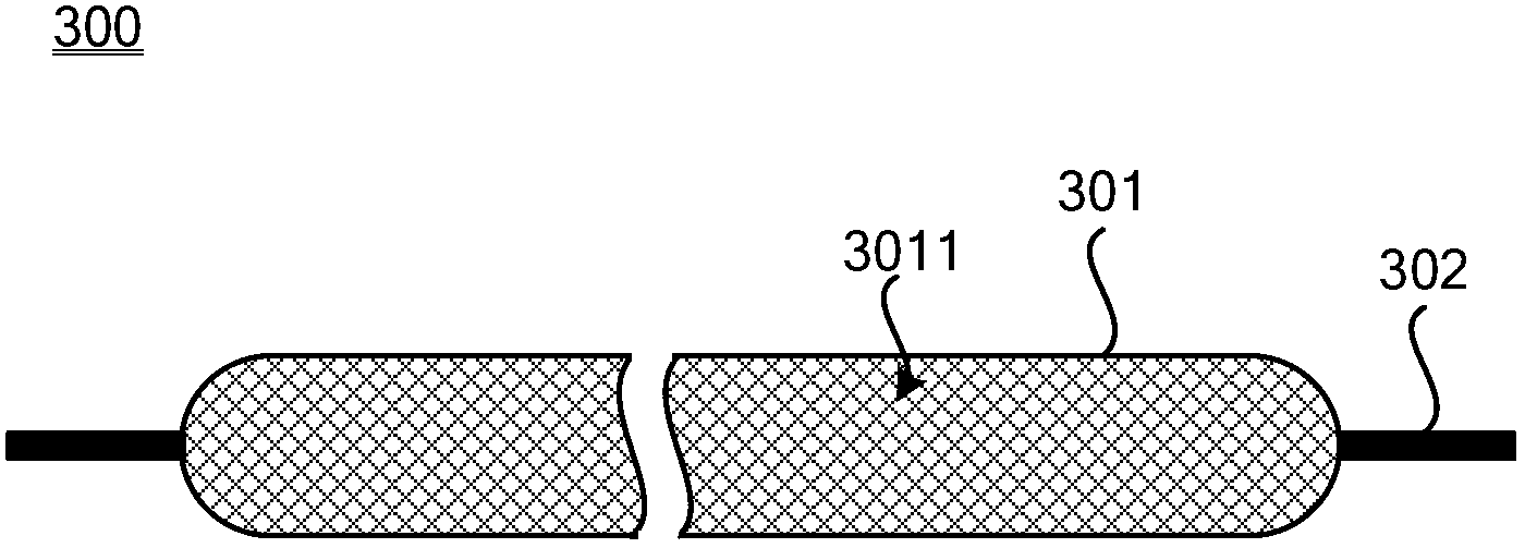
[0031] Such as image 3 As shown, the optical bonding member 300 of this embodiment is used for bonding a display device and a touch device. The optical bonding member 300 includes a capsule structure 301 and an adhesive annular sheet structure 302 located around the capsule structure 301 , wherein the capsule structure 301 is filled with liquid optical glue 3011 . The material for bonding the annular sheet structure 302 and the capsule structure 301 is, for example, PE or PET.

[0032] Such as Figure 4 As shown, when the optical adhesive 300 is bonding the display device 400 and the touch device 500, the capsule structure 301 is located between the display device 400 and the touch device 500, and corresponds to the display area AA of the display device 400 , the adhesive annular sheet structure 302 is located in the peripheral area of ​​the display area AA of the display device 400 , and is used for bonding the display device 400 and the touch device 500 together.

[0033...

Embodiment 2

[0037] Such as Figure 5 As shown, the touch display device 600 of this embodiment includes: a display device 400, a touch device 500, and the optical bonding member 300, and the display device 400 and the touch device 500 are bonded through the adhesive annular sheet Structure 302 is glued together. The capsule structure 301 is filled with liquid optical glue 3011, and the thickness H1 of the capsule structure 301 after filling the liquid optical glue 3011 is 0.2mm˜0.3mm.

[0038] The optical adhesive in this embodiment is basically the same as the optical adhesive in Embodiment 1. The following only describes the differences between the optical adhesive in this embodiment and the optical adhesive in Embodiment 1. Other Part of it can refer to Example 1.

[0039] continue to refer Figure 5In order to ensure the stability of bonding of the touch display device 600 , after the touch display device 600 is assembled, the peripheral thickness H2 of the optical adhesive member ...


PUM

PropertyMeasurementUnit
Thicknessaaaaaaaaaa

Abstract

The invention discloses an optical bonding member and a touch display device. The optical bonding member is used for bonding the display device and the touch device together. The optical bonding member comprises: a cystic structure filled with a liquid optical adhesive and an adhesive annular sheet structure around the cystic structure; wherein the refractive index of the liquid optical adhesive is 90%-110% of that of a substrate of the touch device. The touch display device composed of the optical adhesive member provided by the present invention can effectively suppress light scattering caused by air gap and does not increase the process steps. The touch display device has reworkability, and can effectively reduce production costs.

Description

technical field [0001] The invention relates to flat panel display technology, in particular to an optical bonding piece and a touch display device. Background technique [0002] With the increasing number of multimedia information query devices, touch display devices have received more and more attention due to their many advantages such as firmness and durability, fast response speed, space saving, and easy communication. With this touch display technology, the user can realize the corresponding operation only by lightly touching the icon or text on the display screen with his finger, thus making the human-computer interaction more straightforward. [0003] Such as figure 1 As shown, the touch display device 100 includes a display device 101 and a touch device 102 . The touch device 102 is connected to the display device 101 through the “口” glue 103 . The "口" glue 103 is a double-sided adhesive tape with an opening in the middle, which exposes the display device 101 , a...

Claims


Application Information

Patent Timeline
IPC IPC(8): C09J7/00C09J7/02
Inventor 吴超
Owner SHANGHAI AVIC OPTOELECTRONICS
Why Eureka
Try Eureka