
Systems and methods for confining a high temperature plasma with a magnetic field configuration having a zero magnetic field region

A plasma and plasma gun technology, applied in the field of plasma physics, can solve the problems of unfavorable fusion reactor economical operation, low fusion reactor confinement efficiency, interchange instability, etc., to achieve suppression of interchange instability, The effect of simple design and reduced volume

Inactive Publication Date: 2016-07-06
哈工大(张家港)智能装备及新材料技术产业化研究院有限公司
View PDF7 Cites 0 Cited by
  • Summary
  • Abstract
  • Description
  • Claims
  • Application Information

AI Technical Summary

Problems solved by technology

But the traditional magnetic field configuration (tokamak, stellarator and other devices) has a significant disadvantage, that is, the plasma and the magnetic field "blend" with each other, and the plasma diamagnetism causes various forms of instabilities, especially the mutual change instability
Taking tokamak and stellarator as examples, they can only operate stably under the condition of parameter β≈0.05. Obviously, the confinement efficiency of fusion reactor is not high, which is not conducive to the economical operation of fusion reactor

Method used


Image

  • Systems and methods for confining a high temperature plasma with a magnetic field configuration having a zero magnetic field region
  • Systems and methods for confining a high temperature plasma with a magnetic field configuration having a zero magnetic field region
  • Systems and methods for confining a high temperature plasma with a magnetic field configuration having a zero magnetic field region

Examples


Embodiment Construction

[0042] The above and other technical features and advantages of the present invention will be further described below in conjunction with the accompanying drawings. Apparently, the described embodiments are only used to explain the present invention, not to limit the scope of the present invention.

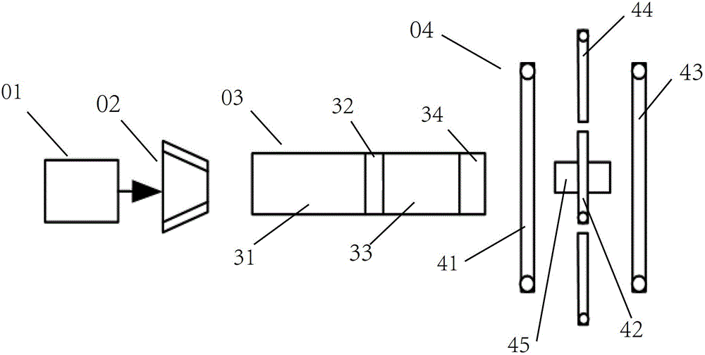
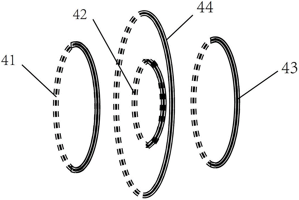
[0043] see figure 1 , is a system structure diagram of the confined high-temperature plasma of the present invention. From figure 1It can be seen from the figure that the system for confining high-temperature plasma of the present invention includes a high-voltage pulse power supply 01 , a plasma gun 02 , a full plasma channel 03 and a magnetic trap coil 04 .

[0044] Wherein, the high-voltage pulse power supply 01 is connected with the plasma gun 02 to supply power for the plasma gun 02 . During implementation, a neutral gas is introduced into the plasma gun 02, and under the action of the high-voltage pulse power supply 01, the neutral gas is excited and ionized, thereby gene...


PUM


Abstract

The invention discloses a system and method using a magnetic field configuration with a zero magnetic field area to restrain high-temperature plasma. The system using the magnetic field configuration with the zero magnetic field area to restrain the high-temperature plasma comprises a plasma gun, a high-voltage pulse power source, a full-plasma channel and a magnetic trap coil, wherein the plasma gun is filled with neutral gases, and is used for generating and transmitting plasma beams, the high-voltage pulse power source is used for providing electricity for the plasma gun, the full-plasma channel is arranged opposite to an outlet of the plasma gun, and is used for transporting the plasma beams transmitted by the plasma gun, and injecting the plasma beams into the magnetic trap coil, and the magnetic trap coil is arranged opposite to an outlet of the full-plasma channel, and is used for generating the ring-shaped magnetic field configuration. A ring-shaped area on the periphery of the ring-shaped magnetic field configuration is a barrier magnetic field, and the central area of the ring-shaped magnetic field configuration is a low-intensity magnetic field area with the zero magnetic field area. A chute coil is further arranged in the full-plasma channel. Due to the fact that the direction of a magnetic field generated by the chute coil and the direction of the barrier magnetic field are opposite, the plasma can easily enter the low-intensity magnetic field area, and then the plasma is stably restrained in the low-intensity magnetic field area.

Description

technical field [0001] The invention relates to the field of plasma physics, in particular to a system and method for confining high-temperature plasma with a magnetic field configuration with a zero magnetic field region. Background technique [0002] Plasma physics is a subject that studies the formation, properties and laws of motion of plasma. One of its application prospects is in controlled thermonuclear fusion, that is, by using a magnetic field with a special structure to confine high-temperature plasma, so as to achieve continuous nuclear fusion reaction. [0003] In the conception of magnetic confinement fusion, the configuration of the magnetic field used to confine high-temperature plasma is one of the key factors. So far, a variety of magnetic confinement methods have been proposed in the international fusion community, and their magnetic field configurations are divided into two types: the open magnetic mirror field and the closed ring configuration magnetic f...

Claims


Application Information

Patent Timeline
Patent Type & Authority Patents(China)
IPC IPC(8): H05H1/10
CPCY02E30/10
Inventor 佟为明金显吉李中伟赵志衡黄桂香林景波刘勇
Owner 哈工大(张家港)智能装备及新材料技术产业化研究院有限公司
Learn More