Foot Profile Measuring Instrument

A contour measurement and foot shape technology, which is applied to the measurement device, clothing, and application of feet or shoe lasts, and can solve problems such as the measurement of the outer contour of the human foot shape.

Active Publication Date: 2016-08-17
3D CAMEGA
View PDF4 Cites 1 Cited by
  • Summary
  • Abstract
  • Description
  • Claims
  • Application Information

AI Technical Summary

Problems solved by technology

The purpose is to solve the problem of human foot contour measurement

Method used


Image

  • Foot Profile Measuring Instrument
  • Foot Profile Measuring Instrument
  • Foot Profile Measuring Instrument

Examples


Embodiment Construction

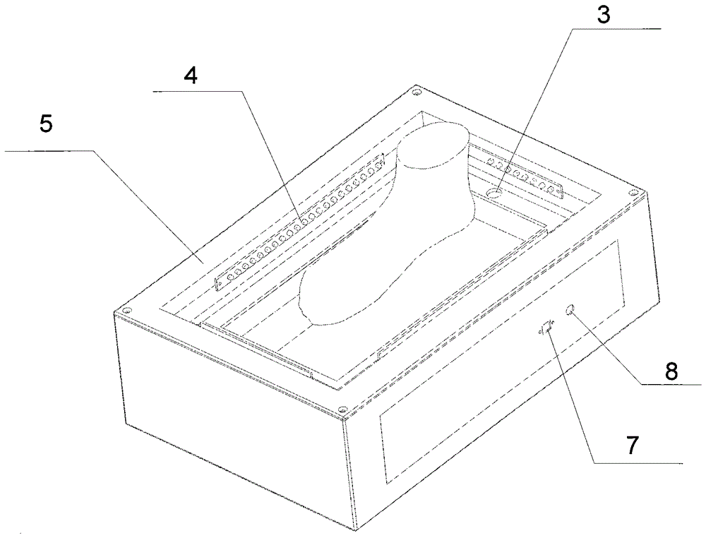
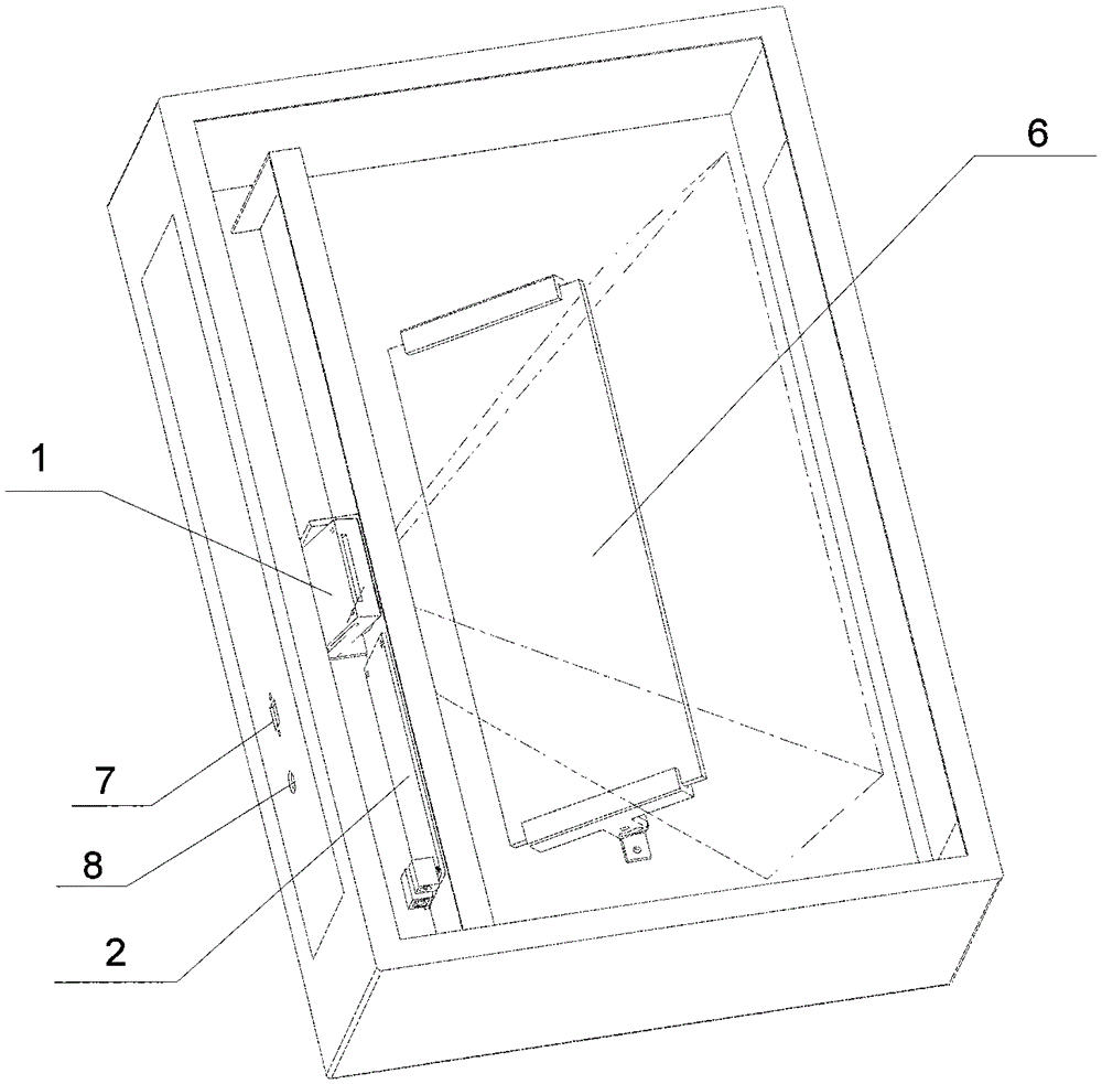
[0018] refer to figure 1 , figure 2 The structure of this foot profile measuring instrument includes (1) narrow-band filter camera lens (or infrared camera lens), (2) COMS capture sensor main control board, (3) electronic induction switch, (4) infrared profile lighting group, (5) Mechanical cover with transparent glass, (6) Mirror (7) Transmission port (8) Power input port. The integration method of this leg-type profile measuring instrument is to combine (1) narrow-band filter camera lens (or infrared camera lens) with (5) glass horizontal plane with transparent glass mechanical cover and (6) mirror, according to the theoretical light imaging angle Fasten firmly. Connect (2) COMS capture sensor main control board with (1) narrow-band filter camera lens (or infrared camera lens), (4) infrared contour lighting group, (7) transmission port, (3) electronic sensor switch, ( 8) Power input port connection.

[0019] When the power is turned on, the device enters the working sta...


PUM


Abstract

The invention relates to a foot model profile meter. The foot model profile meter structurally comprises a COMS (complementary metal oxide semiconductor) image sensor control panel, a narrow-band filter camera lens (or infrared camera lens), an electronic induction switch, infrared profile lighting groups, a mechanical housing with transparent glass, a reflective mirror, a transmission port and the like. The foot model profile meter is especially developed aiming at external profiles of footprints, and is a device with high 'optical-mechanical-electrical' integration. Interference of ambient light is filtered, so that acquired images cannot be affected by the ambient light to be distorted; and an image acquisition device cannot be affected by color, and for users wearing dark socks, external profile data of feet can be well acquired. In addition, the foot model profile meter has a point-and-shoot automatic photographing acquisition function; and when a foot model is stepped on a glass plate, the electronic induction switch sends a photographing command automatically, so that the meter is not intervened manually to pick up images automatically, and finally actual foot model size information and a foot model external profile diaphragm with a black base and white edges are outputted.

Description

technical field [0001] The invention is a non-contact three-dimensional measuring instrument involving technologies such as optics, machinery, electronics, and computer communication, and is a high-tech device that solves the problem of foot shape contour measurement. Background technique [0002] According to the data, the manufacturing center of the international shoe industry began to shift from the United States in the 1950s, first to Japan, to Taiwan and South Korea in the 1970s and 1980s, and to mainland China after the 1990s. At the same time, emerging bases such as Vietnam and India were also born. The process of industrial transfer is actually a process of chasing cost advantages. From the point of view of the entire international shoe-making production pattern, in the past 20 years, the shoe-making industries in mainland China, Vietnam, India and other Asian regions have developed very rapidly, accounting for more than 80% of the world's shoe production, and have b...

Claims


Application Information

Patent Timeline
Patent Type & Authority Patents(China)
IPC IPC(8): A43D1/02
Inventor 白曦东张志波
Owner 3D CAMEGA
Why Eureka
Try Eureka