
Chassis drive system control method and device

A control method and a technology of a control device, which are applied in the field of vehicles, can solve problems such as driver misoperation and flameout, and achieve the effects of reducing operator fatigue, better energy-saving performance, and improving the degree of automation

Active Publication Date: 2013-09-04
ZOOMLION HEAVY IND CO LTD
View PDF5 Cites 0 Cited by
  • Summary
  • Abstract
  • Description
  • Claims
  • Application Information

AI Technical Summary

Problems solved by technology

[0004] The purpose of the present invention is to provide a control method and device for a chassis drive system to solve the problem of flameout caused by driver's misoperation in the prior art

Method used


Image

  • Chassis drive system control method and device
  • Chassis drive system control method and device
  • Chassis drive system control method and device

Examples


Embodiment Construction

[0024] Embodiments of the invention are described in detail below, but the invention can be practiced in many different ways as defined and covered by the claims.

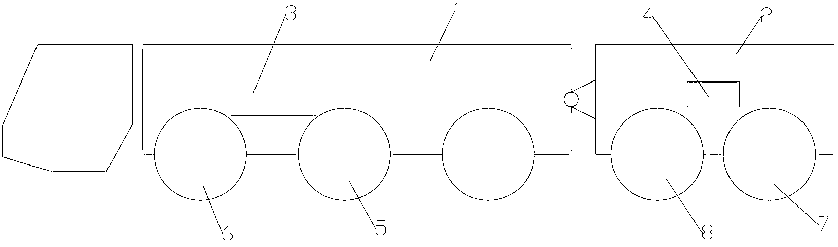
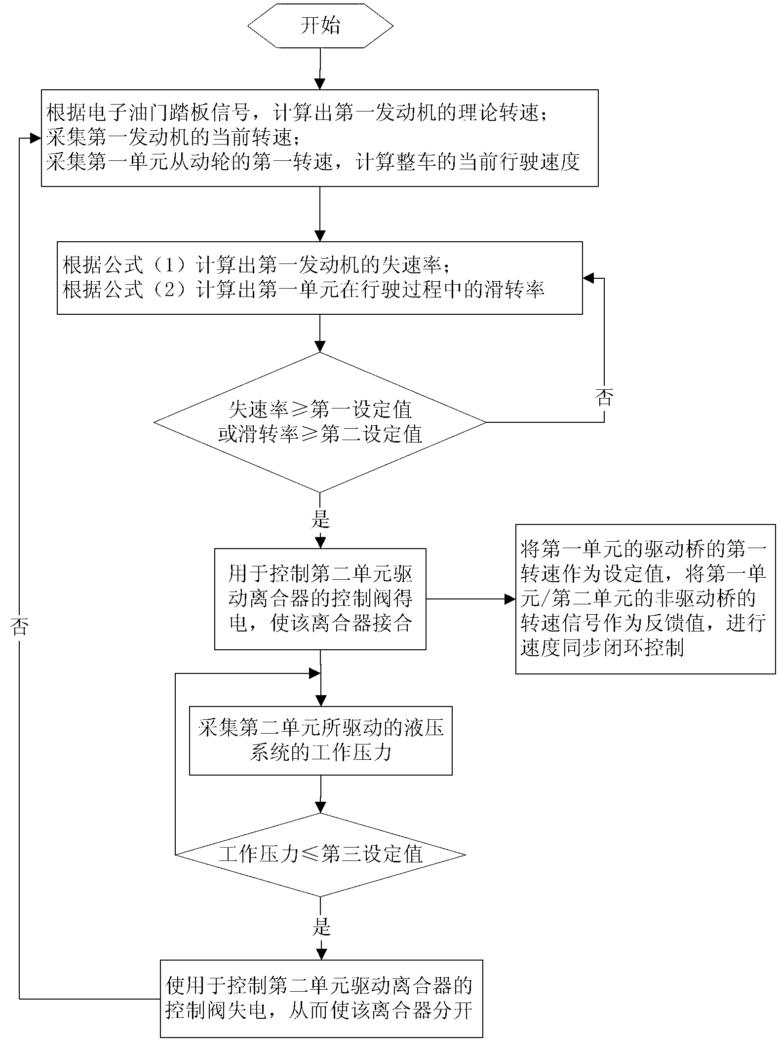
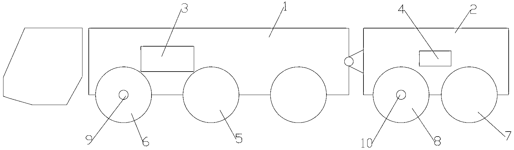
[0025] In some vehicles (such as super-large-tonnage all-terrain cranes, etc.), because the engine manufacturer does not have a matching engine, or because the matching engine installation size is limited, or for energy-saving considerations, dual-power (first engine and the second engine), in which the main power source (the first engine) is arranged in the first unit for driving the vehicle on a smooth road, and the auxiliary power source (the second engine) is arranged in the second unit, It is used to provide auxiliary power for the first unit in the uphill working condition of the whole vehicle or on rough roads. The present invention provides an automatic control method and device for the realization of separation and separation of main and auxiliary power sources and speed synchronization according to the ro...


PUM


Abstract

The invention provides a chassis drive system control method and device. The chassis drive system control method includes: judging a first engine is over-loaded or not according to stall rate of the first engine and / or judging whether an automobile slips or not according to slippage rate of the automobile; and controlling power output of a second engine under the condition of overload of the first engine and / or slippage of the automobile. According to driving road condition of the integral automobile, the second engine is automatically started and stopped, so that right switching time can be found, automatic matching of the first and second engines can be realized, operation fatigue of drivers is alleviated, automation degree of the integral automobile is improved, energy is more saved, and flameout caused by misoperation is avoided.

Description

technical field [0001] The present invention relates to the field of vehicles, and more specifically, to a control method and device for a chassis drive system. Background technique [0002] Such as figure 1 As shown, the chassis of the super-large tonnage all-terrain crane includes a first unit 1 and a second unit 2, wherein a first engine 3 is arranged in the first unit 1, and a second engine 4 is arranged in the second unit 2 . The crane is driven by the first engine 3 and the second engine 4 to travel on the road. The first unit 1 has a first drive axle 5 and a first non-drive axle 6 , and the second unit 2 has a second drive axle 7 and a second non-drive axle 8 . [0003] Among them, the first engine 3 is used as the main power to drive the whole vehicle to run on a smooth road, and the second engine 4 is used as the auxiliary power. Or personal perception, operate the manual button to switch. In the process of manual switching by the driver, it is difficult to gra...

Claims


Application Information

Patent Timeline
IPC IPC(8): B60W30/18
Inventor 李雄李英智张建军刘伟李义
Owner ZOOMLION HEAVY IND CO LTD
Features
  • Generate Ideas
  • Intellectual Property
  • Life Sciences
  • Materials
  • Tech Scout
  • Unparalleled Data Quality
  • Higher Quality Content
  • 60% Fewer Hallucinations
Learn More