Eureka AIR delivers breakthrough ideas for toughest innovation challenges, trusted by R&D personnel around the world.

Led backlight driving circuit, liquid crystal display device and a driving method

A technology of backlight drive circuit and LED light bar, which is applied in the direction of electric lamp circuit layout, lighting device, light source, etc., can solve the problems of high cost, large number of partitions, cost proportional to the number of partitions, etc., to reduce hardware cost and improve contrast Effect

Active Publication Date: 2016-03-30
TCL CHINA STAR OPTOELECTRONICS TECH CO LTD
View PDF8 Cites 0 Cited by
  • Summary
  • Abstract
  • Description
  • Claims
  • Application Information

AI Technical Summary

Problems solved by technology

[0007] b. The local dimming of the direct-lit backlight has the advantage of a large number of partitions and a good effect, but the disadvantage is that the cost is proportional to the number of partitions;
[0008] Usually the number of backlight partitions is determined by the number of dimming channels of the backlight driver module that drives the LED strip. Taking a 16-zone backlight as an example, a backlight driver module with 16 dimming channels is required, or cascaded through multiple backlight driver modules Obtained, for a large-sized LCD panel, the number of partitions of the direct-lit backlight is more, which requires a backlight driver module with more dimming channels, and the cost is higher

Method used


Image

  • Led backlight driving circuit, liquid crystal display device and a driving method
  • Led backlight driving circuit, liquid crystal display device and a driving method
  • Led backlight driving circuit, liquid crystal display device and a driving method

Examples


Embodiment 1

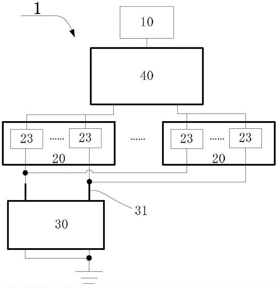
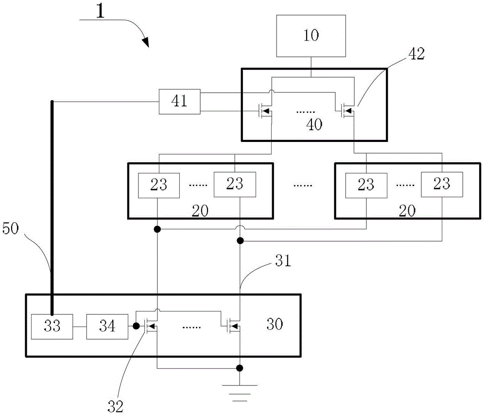
[0043] Such as figure 2 As shown, the switching module 40 includes M switchable controllable switches 42 connected in parallel, the input end of each switchable controllable switch 42 is coupled to the power module 10; the output end is respectively connected to a lamp group 20, and only one switching controllable switch 42 is connected in the same period of time. The switch 42 is turned on. The switching module 40 also includes a delay switching unit 41 coupled with the switching controllable switch 42. After the current lamp group 20 is turned off, the delay switching unit 41 outputs all switching off signals of the controllable switch 42 within a preset delay time, and then The switching controllable switch 42 corresponding to the next lamp group 20 is driven to be turned on.

[0044] The switching module 40 uses a switching controllable switch 42 to control the connection between the lamp group 20 and the power supply, which has a simple solution and low cost. By delay ...

Embodiment 2

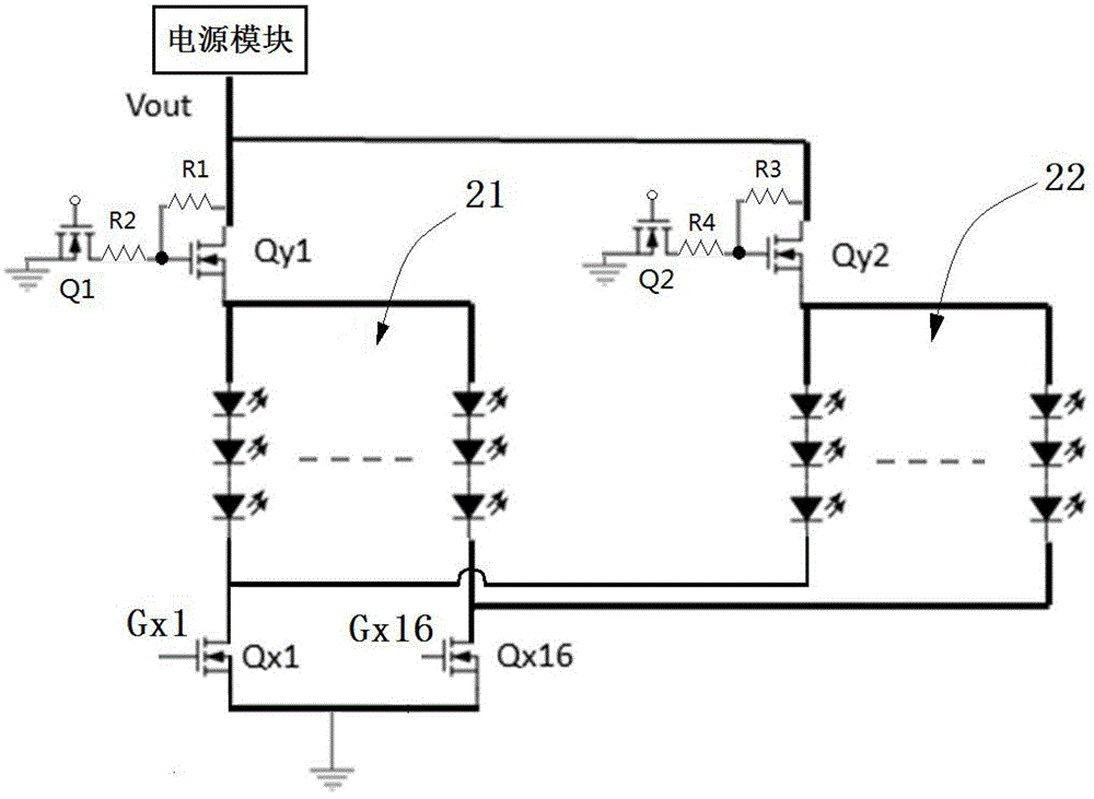
[0050] see image 3 This embodiment is based on the technical solution of two lamp groups. The lamp group includes a first lamp group 21 and a second lamp group 22. Correspondingly, the switching controllable switch includes a first switching controllable switch coupled with the first lamp group 21. Qy1, the second switching controllable switch Qy2 coupled with the second lamp group 22, the switching channel includes a first control switch Q1 and a second control switch Q2; the LED backlight drive circuit also includes a first resistor R1, a second resistor R2 , a third resistor R3 and a fourth resistor R4; the first resistor R1 is connected in series between the control terminal of the first switch Qy1 and the output terminal of the power module; one terminal of the second resistor R2 is coupled to The control terminal of the first switchable controllable switch Qy1, and the other terminal is grounded through the first control switch Q1; the third resistor R3 is connected in ...

Embodiment 3

[0060] Such as Figure 5 As shown, the present invention also discloses a driving method of an LED backlight driving circuit. The LED backlight driving circuit includes a power module, an LED light bar, and a constant current driving module for driving the LED light bar. The driving method includes

[0061] A. Set up M parallel light groups with N parallel light bars as the unit;

[0062] B. Connect the M strings of LED light bars to the dimming channel of the same constant current drive module; the M strings of LED light bars belong to different light groups;

[0063] C. Control a light group to couple with the power module at the same time period;

[0064] D. Control the conduction of the dimming channel of the constant current drive module during the conduction time of a lamp group;

[0065] M is a positive integer.

[0066] In step C, a dead zone can be added when two adjacent lamp groups are switched, and all lamp groups in this dead zone are extinguished, and the next...


PUM


Abstract

The invention discloses an LED backlight driving circuit, a liquid crystal display device and a driving method. The LED backlight drive circuit includes a power supply module, an LED light bar, and a constant current drive module for driving the LED light bar. The backlight drive circuit also includes a switching module coupled with the power supply module, and M lamp groups arranged in parallel, each The light group includes at least two series of LED light bars arranged in parallel; the input end of each string of LED light bars is coupled to the switching module; the constant current drive module includes a plurality of regulators coupled to the output ends of the LED light bars Light channel, each dimming channel is connected with M strings of LED light bars, and the LED light bars connected to the same dimming channel belong to different light groups; the same string of LED light bars is only coupled to one dimming channel; at the same time There is only one lamp group coupled to the power supply module through the switching module; the M is a positive integer. The invention reduces the hardware cost while improving the contrast ratio.

Description

technical field [0001] The invention relates to the field of liquid crystal display, and more specifically relates to an LED backlight driving circuit, a liquid crystal display device and a driving method. Background technique [0002] Many electronic products are equipped with display devices. There are many indicators for judging the pros and cons of different display devices. Contrast Ratio (hereinafter referred to as CR) is a very important parameter. The higher the contrast, the more vivid the picture and the richer the displayed colors. . A general display device will divide the display gray scale into 255 levels, and CR is equal to the ratio of the brightness of 255 gray scale to the brightness of 0 gray scale, the formula is as follows: [0003] CR=255 grayscale brightness / 0 grayscale brightness [0004] For TFT-LCD, the brightness of 255 grayscale is limited by factors such as the maximum brightness of the backlight and the glass transmittance, so it is not easy t...

Claims


Application Information

Patent Timeline
Patent Type & Authority Patents(China)
IPC IPC(8): G09G3/36H05B37/02
CPCG09G3/3406G09G2320/062
Inventor 陈辛洪
Owner TCL CHINA STAR OPTOELECTRONICS TECH CO LTD
Why Eureka
Eureka Blog
Learn More