

Spindle device
A main shaft device and bearing technology, applied in the directions of shafts, bearings, shafts and bearings, etc., can solve the problems of excessive heat in the contact part, wear of sealing parts, and maintenance of waterproof performance.
- Summary
- Abstract
- Description
- Claims
- Application Information
AI Technical Summary
Problems solved by technology
Method used
Image

Examples
no. 1 approach )
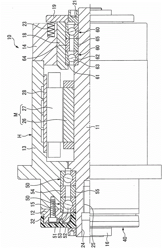
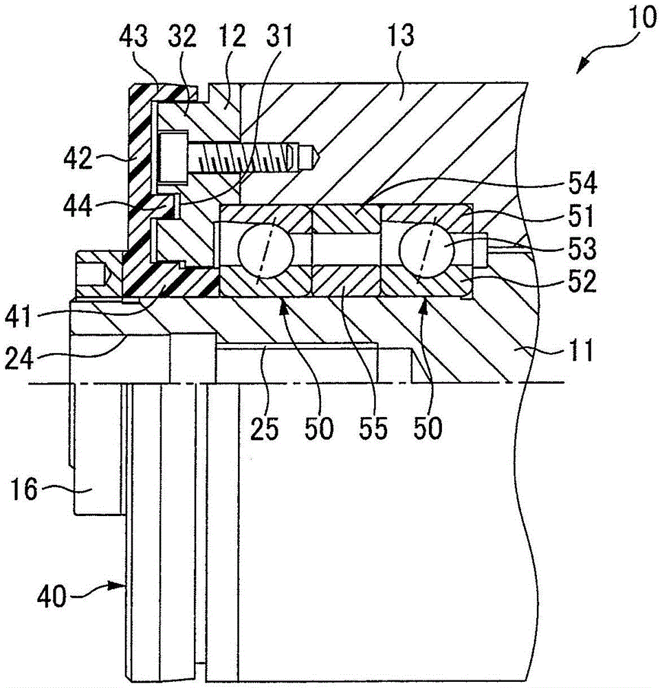
[0252] Such as figure 1 with figure 2 As shown, the spindle device 10 of this embodiment is a built-in motor spindle device for machine tools, and the two rows of front side bearings 50, 50 supporting the tool side (front side) of the rotary shaft 11 and the opposite side of the tool side supporting the rotary shaft 11 Two rows of rear side bearings 60 , 60 on the side (rear side) support the rotating shaft 11 in the housing H in a rotatable manner. The housing H has a front-side bearing outer ring fastening portion 12 , an outer cylinder 13 , and a rear-side housing 14 in this order from the tool side.
[0253] Each front side bearing 50 is an angular contact ball bearing, and each angular contact ball bearing includes an outer ring 51, an inner ring 52, balls 53 as rolling elements arranged to have a contact angle, and a cage not shown in the figure, and each rear side bearing 60 The angular contact ball bearing includes an outer ring 61 , an inner ring 62 , balls 63 as ...
Deformed example 1
[0274] The flinger 40 is not limited to the carbon fiber composite material, and may be formed of a material having a specific modulus larger than that of the rotating shaft 11 . Here, the specific modulus is the value obtained by dividing the longitudinal elastic modulus by the density (specific elastic modulus = E (longitudinal elastic modulus: kgf / m 2 ) / ρ(density: kg / m 3 )).
[0275] For example, when the rotating shaft 11 is formed of metal such as SC material, SCM material, SUS material, AL material, or CU material, the specific modulus is 1.4×10 6 m~2.7×10 6 m, and the flinger 40 is formed of a material having a larger specific modulus than that. The specific modulus of the flinger 40 is larger than the specific modulus of the rotating shaft 11, preferably 5×10 6 More than m, more preferably 8×10 6 more than m. On the other hand, considering the imbalance of stress with the embedded rotating shaft 11, etc., the upper limit is preferably 20×10 in practical applicati...
no. 2 approach )
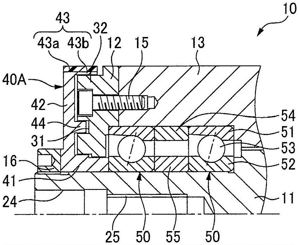
[0287] Next, refer to image 3 A second embodiment of the spindle device will be described. image 3 It is a sectional view of main parts of a spindle device according to a second embodiment of the present invention, and the structure of the oil slinger is different from that of the first embodiment. As for the other parts, they are the same as the spindle device of the first embodiment of the present invention, so the same or equivalent symbols are attached to the same parts, and the description thereof is simplified or omitted.
[0288] The annular portion 43 of the oil slinger 40A of the spindle device 10 according to the present embodiment includes an outer-diameter-side annular portion 43a including the outer peripheral surface of the annular portion 43 and an inner-diameter side located on the inner-diameter side of the outer-diameter-side annular portion 43a. The ring part 43b. The outer diameter side annular portion 43a and the inner diameter side annular portion 43b...
PUM
| Property | Measurement | Unit |
|---|---|---|
| tensile strength | aaaaa | aaaaa |
Abstract
Description
Claims
Application Information