X-ray diagnostic system and X-ray image shooting method

A diagnostic system and image shooting technology, which is applied in the field of X-ray diagnostic system and X-ray image shooting, can solve the problems of high difficulty and complex positioning operation, and achieve the effects of ensuring high accuracy, simplifying the shooting process, and improving shooting efficiency

Active Publication Date: 2013-09-11
LIANYING GUIZHOU MEDICAL TECH CO LTD
View PDF7 Cites 18 Cited by
  • Summary
  • Abstract
  • Description
  • Claims
  • Application Information

AI Technical Summary

Problems solved by technology

[0004] The present invention provides an X-ray diagnostic system to overcome the complex and difficult problem of artificial visual control of the X-ray detector for positioning the position to be measured during the shooting process of the existing medical X-ray diagnostic system.

Method used


Image

  • X-ray diagnostic system and X-ray image shooting method
  • X-ray diagnostic system and X-ray image shooting method
  • X-ray diagnostic system and X-ray image shooting method

Examples


Embodiment 1

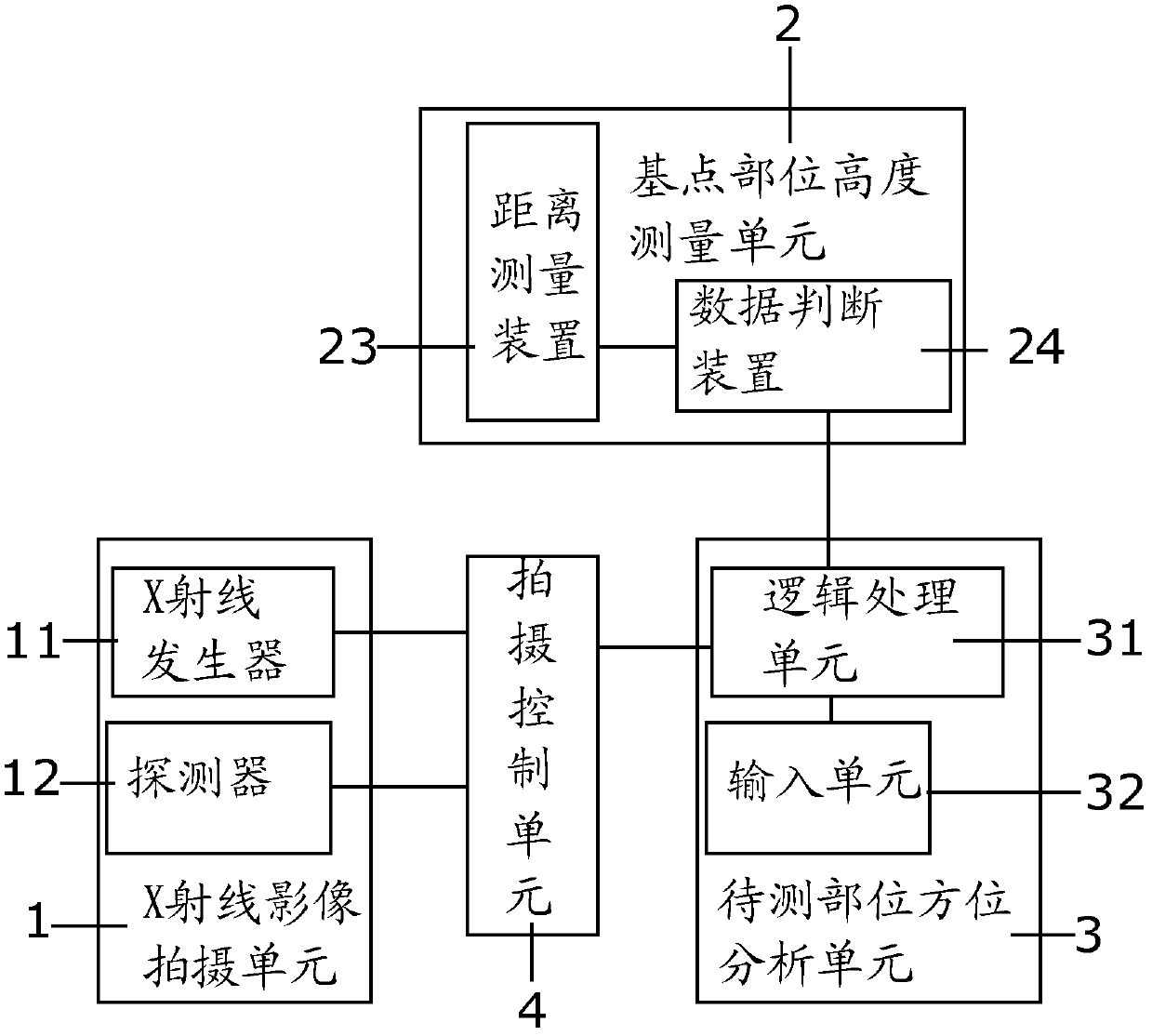
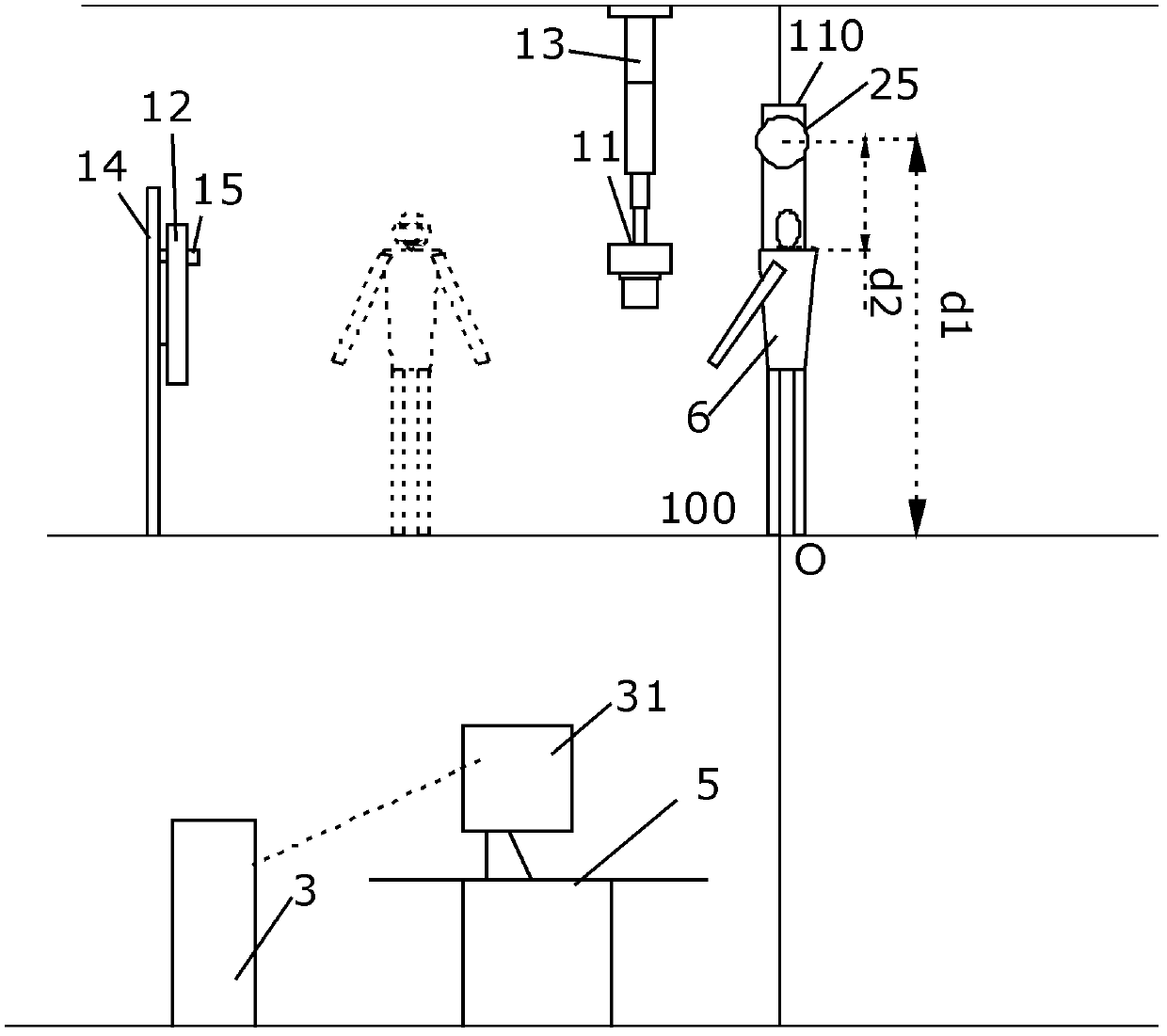
[0057] refer to figure 1 As shown, the X-ray diagnostic system includes: an X-ray image capturing unit 1 , a base point height measuring unit 2 , an orientation analysis unit 3 of a site to be measured, and a shooting control unit 4 . In the present invention, a certain part of the human body is used as a base point, and by acquiring the height data of the base point of the base point, the azimuth parameters of the position to be measured including the position height data of the position to be measured are obtained. The shooting control unit 4 adjusts the movement of the X-ray image capturing unit 1 to the position corresponding to the site to be measured based on the orientation parameters of the site to be tested, so as to complete the shooting of the X-ray image of the site to be tested.

[0058] The specific solution is: the X-ray image capturing unit 1 includes an X-ray generator 11 and a detector 12, and is used for capturing an X-ray image of a site to be measured of a...

Embodiment 2

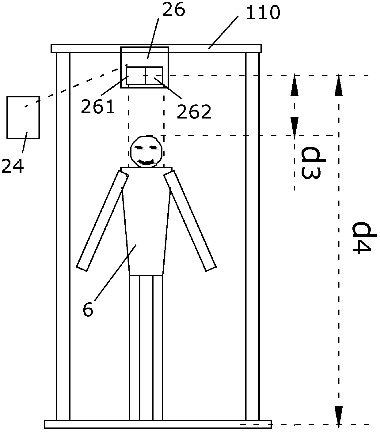
[0082] The technical solution of this embodiment is roughly the same as that of Embodiment 1, the difference is that the reference Figure 4 shown. In this embodiment, the base point height measurement unit 2 includes a body shape image acquisition unit 21 and a height data processing unit 22, the body shape image acquisition unit 21 is connected to the height data processing unit 22, and the height data The processing unit 22 is connected to the logic processing unit 31 . When the height data of the diagnostic object 6 is used as the base point part height data, the body shape image acquiring unit 21 is used to acquire the body shape image of the diagnostic object. The height data processing unit 22 extracts the body shape image, and obtains the height data of the diagnosis object based on the distance between two relative reference points along the height extension direction of the diagnosis object 6 in the body shape image. Specifically, the human body height can be obtai...


PUM


Abstract

The invention provides an X-ray diagnostic system and an X-ray image shooting method. The X-ray image shooting method comprises the steps that firstly, orientation parameters including height data of a basis point part of a certain specific part of a diagnosis object is taken as the reference to acquire orientation parameters including position height data of the to-be-detected part, and a shooting position from the X-ray image shooting device to the to-be-detected part is adjusted based on the orientation parameters. The X-ray diagnostic system comprises an X-ray image shooting unit for shooting the X-ray image on the to-be-detected part of the diagnosis object, a basis point part height measurement unit for acquiring the basis point part height data of the diagnosis object, a to-be-detected part orientation analysis unit for acquiring the orientation parameters of the to-be-detected part based on the basis point part height data, and an X-ray image shooting position shooting control unit controlling an X-ray generator and/or detector to move to the to-be-detected part. According to the X-ray diagnostic system and the X-ray image shooting method, positioning of the X-ray generator and/or detector is automatically controlled through the shooting control unit so as to replace detector positioning adjustment through artificial visual estimation, the X-ray image shooting process is simplified, and the shooting efficiency is improved.

Description

technical field [0001] The invention relates to an X-ray image diagnosis and treatment method, in particular to an X-ray diagnosis system and an X-ray image shooting method. Background technique [0002] Medical X-ray diagnostic system includes X light source and detector. The X-rays emitted by the X-ray source pass through the diagnostic object and then are transmitted to the detector, so as to obtain the in-vivo image of the diagnostic object according to the X-ray images recorded by the detector. Due to the different densities of the parts of the tissues of the diagnostic object, when the X-rays pass through the parts of the tissues, the absorption of the X-ray dose by the parts of the tissues is different. Therefore, after the X-rays pass through the human body, there are large differences in the X-ray images of different parts recorded by the detector. According to the difference of the X-ray images recorded by the detector, the in-vivo image of the diagnosed object c...

Claims


Application Information

Patent Timeline
Patent Type & Authority Applications(China)
IPC IPC(8): A61B6/00
Inventor 庞育杰
Owner LIANYING GUIZHOU MEDICAL TECH CO LTD
Why Eureka
Try Eureka