Press product forming method
A technology of stamping parts and stamping forming, which is applied in the field of stamping parts forming, can solve the problems of flange part wrinkle forming, defects, etc., and achieve the effect of suppressing folds or fold overlapping
- Summary
- Abstract
- Description
- Claims
- Application Information
AI Technical Summary
Problems solved by technology
Method used
Image

Examples
no. 1 Embodiment approach
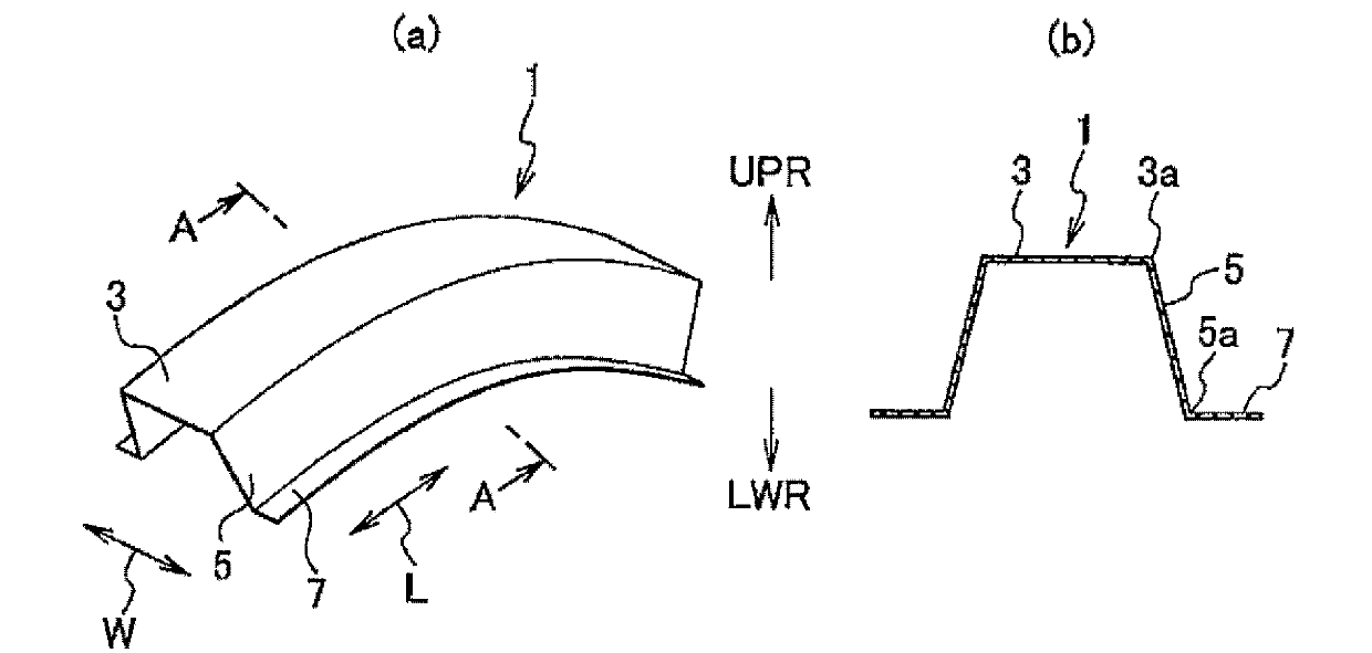
[0041] Such as figure 1 As shown, the curved stamping part 1 of the first embodiment is formed into a cross-sectional hat shape by the following parts: the top part 3 is arranged on the upper side and extends in the longitudinal direction L; The widthwise end edge 3a of the face portion 3 extends obliquely downward (direction intersecting with the top face portion 3); Curved and extended toward the left and right sides.
[0042] Further, the widthwise end edge 3a of the top surface portion 3 is formed along the longitudinal direction L, and is formed in an arc shape that curves upward UPR to protrude in a side view.
[0043] The method for forming a press part according to the present embodiment includes a preliminary forming step, a final forming step, and a flange portion flattening step.
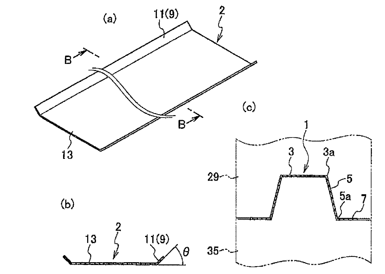
[0044] Preparatory forming steps such as figure 2 Shown in (a) and (b) are the steps of forming the high rigidity portion 9 extending along the longitudinal direction L on both sides ...
Embodiment
[0049] Next, the procedure of forming the bent press part of the first embodiment using a die will be described in detail in comparison with a comparative example.
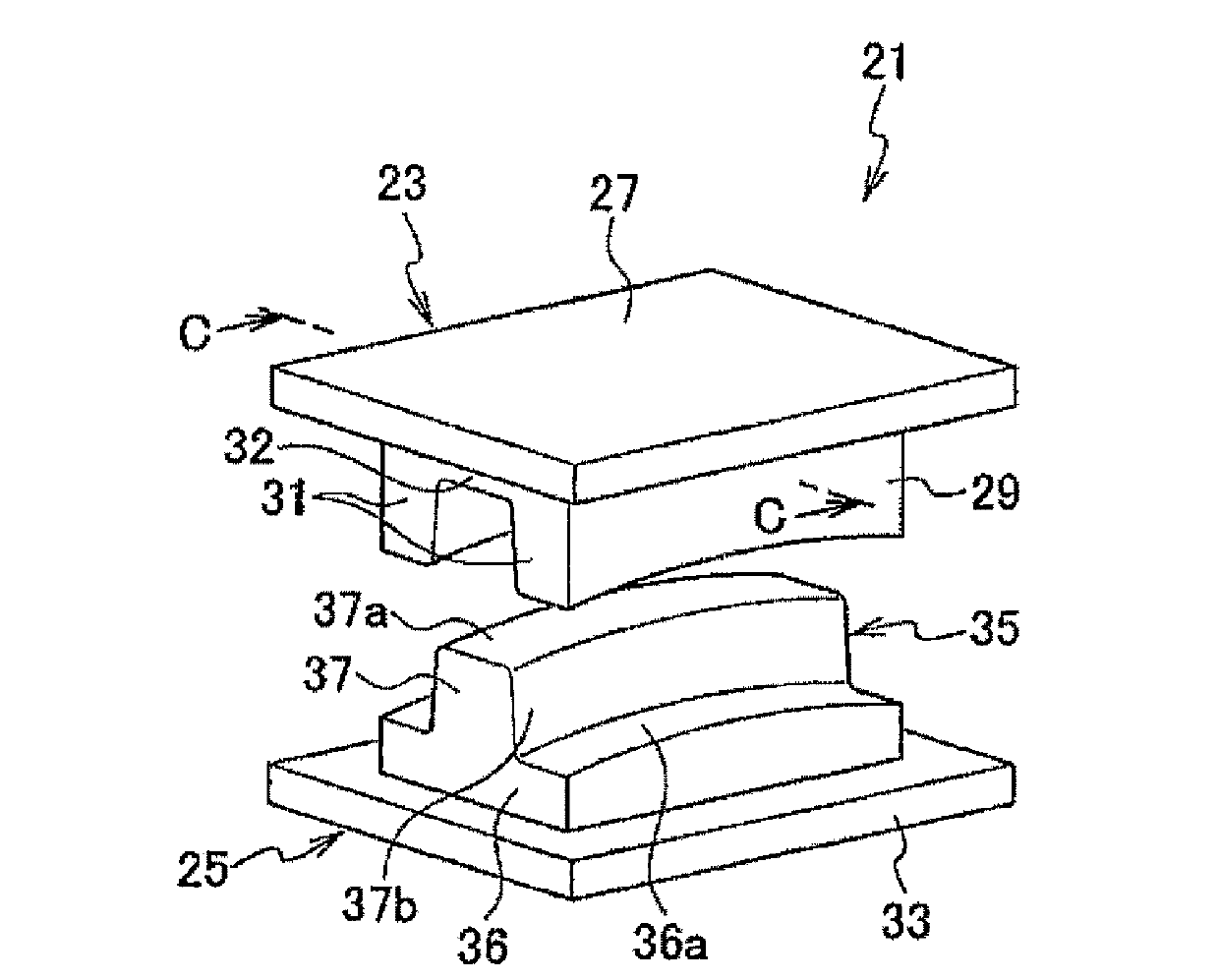
[0050] Such as image 3 As shown, the mold 21 is composed of an upper mold 23 and a lower mold 25 . The upper mold 23 is composed of a mounting plate 27 and an upper molding die 29 provided under the mounting plate 27 . The upper molding die 29 is formed in a U-shape in a front view, and has a pair of left and right upper molding parts 31 extending downward, and a connecting part 32 bridging the upper molding parts 31 and 31. constitute. In addition, the lower die 25 is composed of a mounting plate 33 and a lower molding die 35 provided on the upper side of the mounting plate 33 . The lower forming die 35 is formed in a T-shape in front view, and is composed of flange forming portions 36 on both sides in the left and right direction, and a lower forming portion 37 protruding upward from a central portion in the...
no. 2 Embodiment approach
[0061] Next, the second embodiment will be described, but the same components as those in the first embodiment will be denoted by the same reference numerals, and description thereof will be omitted.
[0062] In the curved stamped part 1 of the first embodiment, the widthwise end edge 3a of the top surface portion 3 is formed along the longitudinal direction L in a side view and is formed in an arc shape that is curved upward UPR to protrude.
[0063] However, the curved press part 51 of the second embodiment, such as Figure 8 As shown in (a), the curved inner widthwise end edge 53a and the curved outer widthwise end edge 53b of the top surface portion 53 are curved in an arc shape along the longitudinal direction L in plan view. in addition, Figure 8 The cross-sectional shape shown in (b) is the same as that of the first embodiment. figure 1 (b) In the same shape, the top surface portion 53 , the side wall portion 55 and the flange portion 57 form a cap shape. In additio...
PUM
 Abstract
Description
Claims
Application Information
 - R&D
- Intellectual Property
- Life Sciences
- Materials
- Tech Scout
- Unparalleled Data Quality
- Higher Quality Content
- 60% Fewer Hallucinations
Browse by: Latest US Patents, China's latest patents, Technical Efficacy Thesaurus, Application Domain, Technology Topic, Popular Technical Reports.
© 2025 PatSnap. All rights reserved.Legal|Privacy policy|Modern Slavery Act Transparency Statement|Sitemap|About US| Contact US: help@patsnap.com