Gate cutting device

A gate and roller shaft technology, applied in the field of cutting devices, can solve problems such as unfavorable use by workers, disassembly and maintenance, complex structure of gate cutting equipment, easy shaking of workpieces, etc. Effect

Inactive Publication Date: 2013-09-11
中发输配电设备(平湖)有限公司
View PDF8 Cites 3 Cited by
  • Summary
  • Abstract
  • Description
  • Claims
  • Application Information

AI Technical Summary

Problems solved by technology

[0004] The present invention solves the problem that the gating cutting equipment in the prior art has a complicated structure, is heavy, does not use workers to use, disassemble and maintain, and the workpiece is easy to shake during the cutting process.

Method used


Image

  • Gate cutting device
  • Gate cutting device
  • Gate cutting device

Examples


Embodiment Construction

[0010] The present invention will be further described below in conjunction with drawings and embodiments.

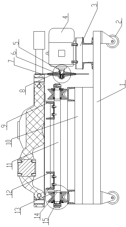
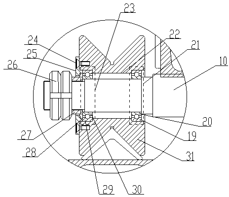
[0011] As shown in the figure, it includes a base 1, a motor 4, a cutter head mechanism and a roller shaft mechanism. The right part of the base 1 is provided with a motor base 3, and the motor 4 is fixed on the motor base 3. The left end of the motor 4 is A motor rotating shaft 5 is provided, and the cutterhead mechanism is fixed on the motor rotating shaft 5; a guide rail frame 10 is provided on the left part of the base 1, and the roller shaft mechanism is arranged on the top of the rail frame 10, through the roller The shaft fixing mechanism is fixed; the bottom of the base 1 is provided with a universal wheel 2 .

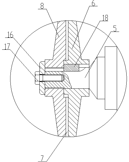
[0012] In this embodiment, the cutterhead mechanism includes a left cutterhead 8, a right cutterhead 6 and a saw blade milling cutter 7, and the right cutterhead 6 is set on the motor rotating shaft 5 and fixed by a flat key 18 , the left cutter head 8 ...


PUM


Abstract

The invention discloses a gate cutter comprising a base, a motor, a cutter mechanism and a roller shaft mechanism. The gate cutting device is characterized in that a motor base is disposed on the right of the base, the motor is fixed on the motor base, a motor rotating shaft is disposed at the left end of the motor, the cutter mechanism is fixed on the motor rotating shaft, a guide rail carrier is disposed on the left of the base, the roller shaft mechanism is arranged above the guide rail carrier and fixed through a roller shaft fixing mechanism, and universal wheels are disposed below the base. The gate cutting device has the advantages that cast gates can be cut effectively, workpieces rarely shake, machining errors are reduced effectively, and the gate cutting device is simple in structure and convenient and flexible to use.

Description

technical field [0001] The invention relates to the field of cutting devices, in particular to a gate cutting device. Background technique [0002] At present, after the casting is demoulded, the gate needs to be cut. The existing equipment has a complex structure, is heavy, does not use the use of workers, disassembles and maintains it, and the workpiece is easy to shake during the cutting process, resulting in The workpiece has machining errors. Contents of the invention [0003] The object of the present invention is to provide a gate cutting device. [0004] The invention solves the problems in the prior art that the gating cutting equipment is complex and heavy, does not require workers to use, disassemble and maintain, and the workpiece is easy to shake during the cutting process. [0005] The technical solution adopted by the present invention to solve the technical problem is: it includes a base, a motor, a cutter head mechanism and a roller shaft mechanism, the ...

Claims


Application Information

Patent Timeline
IPC IPC(8): B22D31/00
Inventor 周大全李德寿包行方
Owner 中发输配电设备(平湖)有限公司
Why Eureka
Try Eureka