Current-opposition-influence-resistant composite differential protection method for power transmission line

A transmission line and differential protection technology, which is applied to emergency protection circuit devices, electrical components, etc., can solve problems such as differential current reduction, overheating and fuse of transmission lines, and unsatisfied current differential protection criteria

Active Publication Date: 2013-09-11
STATE GRID CORP OF CHINA +3
View PDF6 Cites 3 Cited by
  • Summary
  • Abstract
  • Description
  • Claims
  • Application Information

AI Technical Summary

Problems solved by technology

Since the inductance of the transmission line is compensated by the installation of series compensation capacitors, after a fault occurs inside the transmission line, the current phase of the fault phase will lead the phase of the voltage phase of the fault phase, that is, the current phase will be reversed, resulting in a decrease in the differential current and an increase in the braking current. If the current differential protection criterion is not satisfied, the current differential protection cannot operate correctly to jump off the fault line, and cannot isolate the fault line from the grid in time, resulting in a large current passing through the transmission line and power equipment for a long time, causing transmission line failure. Overheating fuse, overheating and burning of electrical equipment or damage to insulation

Method used


Image

  • Current-opposition-influence-resistant composite differential protection method for power transmission line
  • Current-opposition-influence-resistant composite differential protection method for power transmission line
  • Current-opposition-influence-resistant composite differential protection method for power transmission line

Examples


Embodiment Construction

[0016] The technical solution of the present invention will be further described in detail according to the accompanying drawings.

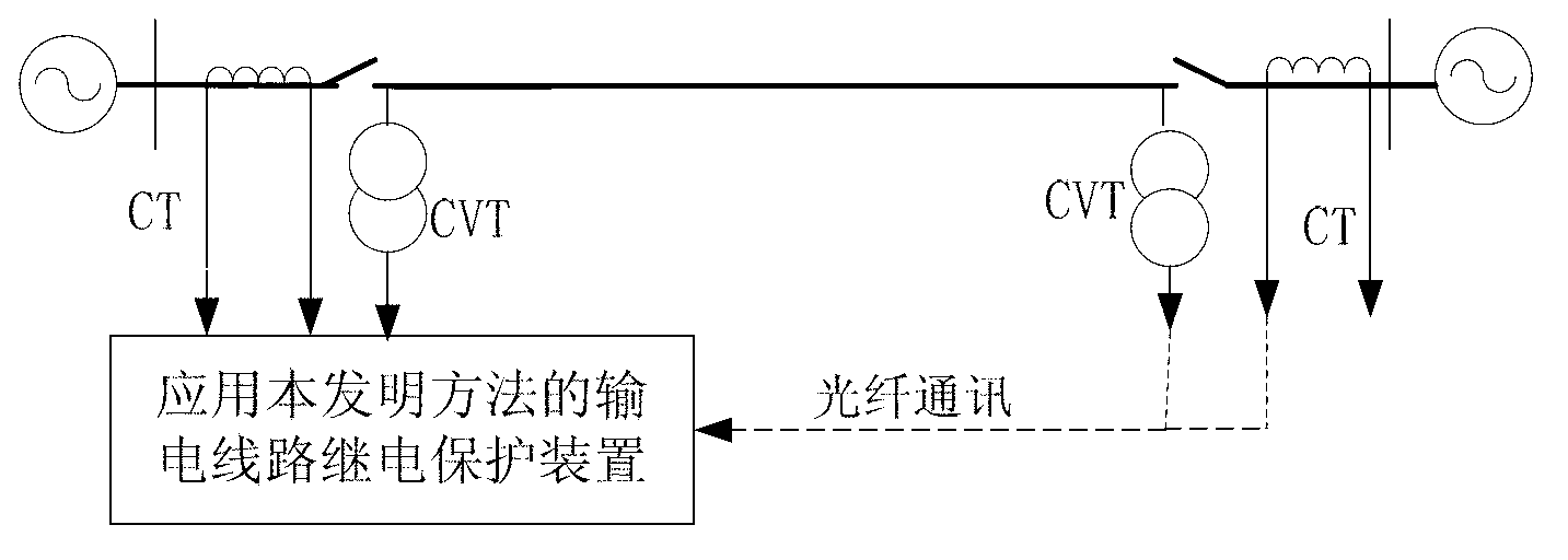
[0017] figure 1 It is a schematic diagram of the line transmission system applying the present invention. The protection device measures the A-phase voltage of the transmission line at the protective installation of the m substation when the transmission line is in normal operation , Phase B voltage , Phase C voltage , to measure the A-phase voltage of the transmission line at the protective installation of substation n when the transmission line is in normal operation , Phase B voltage , Phase C voltage .

[0018] The protection device measures the A-phase current of the transmission line at the protective installation of the m substation after the transmission line fails , Phase B current , Phase C current , to measure the A-phase current of the transmission line at the protective installation of substation n after the transmi...


PUM


Abstract

The invention discloses a current-opposition-influence-resistant composite differential protection method for a power transmission line. The method is characterized in that an imaginary portion of a ratio of each phase voltage obtained during normal running of the power transmission line to a corresponding phase current obtained after the power transmission line fails is computed at first, and phase currents at two ends of the power transmission line and the imaginary portion of the ratio of each phase voltage obtained during normal running of the power transmission line to the corresponding phase current obtained after the power transmission line fails form current differential protection criteria. The current-opposition-influence-resistant composite differential protection method has the advantages that the problem of influence of current reversal to the performance of differential protection actions for the currents is eliminated in principle, and the current-opposition-influence-resistant composite differential protection method is applicable to power transmission lines with series compensation capacitors; accurate and reliable actions can be performed by the method when faults occur on the inside of the power transmission line with series compensation capacitors, and correct and reliable locking can be performed by the method when faults occur on the outside of the power transmission line with the series compensation capacitors.

Description

technical field [0001] The invention relates to the technical field of electric power system relay protection, in particular to a composite differential protection method for transmission lines against the influence of current reverse phase. Background technique [0002] Because it is not affected by the power system operation mode and grid structure and has a natural phase selection function, the current differential protection has always been the main protection of various voltage levels of transmission lines. Series compensation capacitors are often installed on transmission lines with voltage levels of 500kV and above to compensate for the inductance of transmission lines to increase transmission capacity, shorten electrical connections, and improve power system stability. Since the inductance of the transmission line is compensated by installing the series compensation capacitor, after a fault occurs inside the transmission line, the current phase of the fault phase wil...

Claims


Application Information

Patent Timeline
Patent Type & Authority Applications(China)
IPC IPC(8): H02H7/26
Inventor 曾惠敏林富洪
Owner STATE GRID CORP OF CHINA
Why Eureka
Try Eureka