Clamping tool for trimming wing leading edge covering

A technology for clamping tooling and leading edge skin, applied in workpiece clamping devices, manufacturing tools, etc., to achieve the effect of increasing the adjustment range, significant economic benefits, and reducing design and manufacturing costs

Active Publication Date: 2013-09-18
COMAC +1
View PDF4 Cites 21 Cited by
  • Summary
  • Abstract
  • Description
  • Claims
  • Application Information

AI Technical Summary

Problems solved by technology

[0003] The purpose of the present invention is to provide a clamping tool for trimming the leading edge of the wing to solve the defects of the existing hard tool

Method used


Image

  • Clamping tool for trimming wing leading edge covering
  • Clamping tool for trimming wing leading edge covering
  • Clamping tool for trimming wing leading edge covering

Examples


Embodiment Construction

[0052] In the following detailed description of the preferred embodiment, reference is made to the accompanying drawings which form a part hereof. The accompanying drawings show, by way of example, specific embodiments in which the invention can be practiced. The illustrated embodiments are not intended to be exhaustive of all embodiments in accordance with the invention. It is to be understood that other embodiments may be utilized and structural or logical changes may be made without departing from the scope of the present invention.

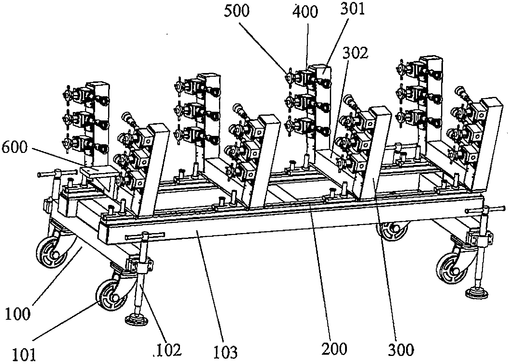
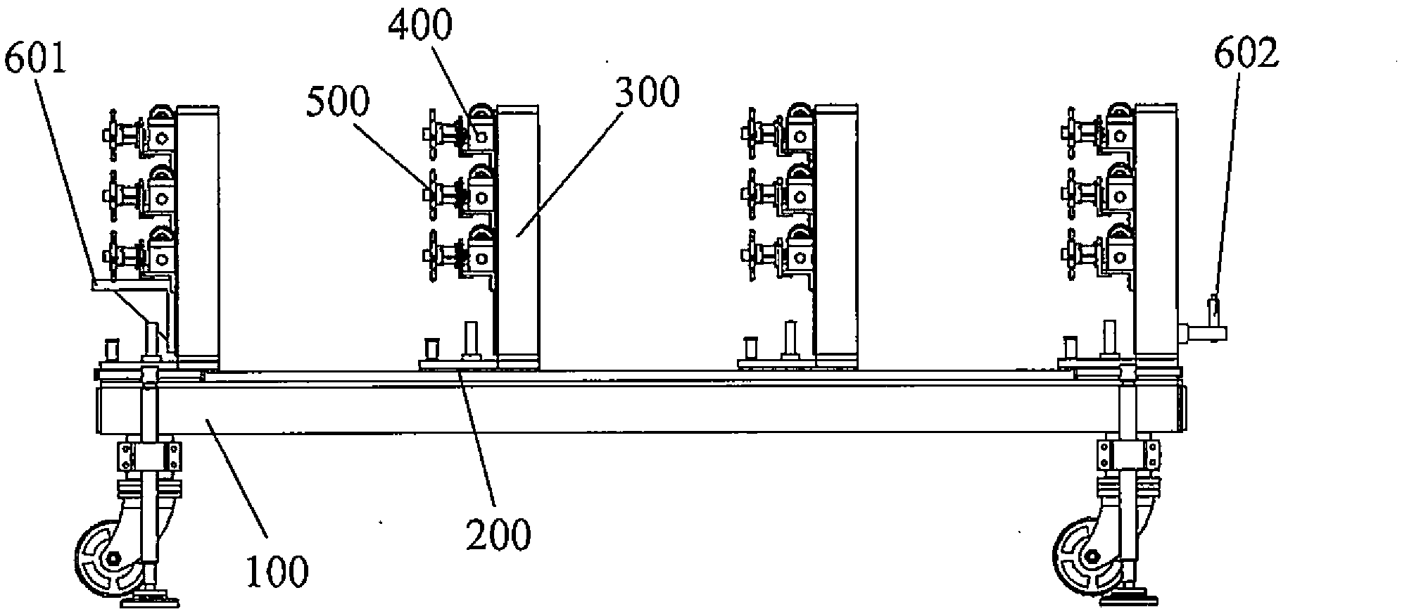
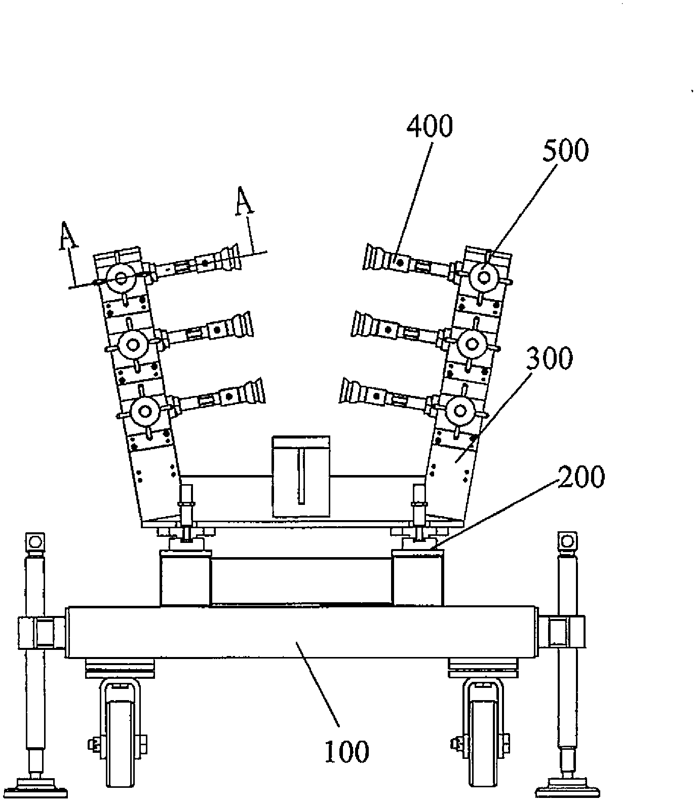
[0053] see Figure 1 to Figure 6 As shown, according to the present invention, the clamping tool for wing-type leading edge skin trimming includes a base 100, two sliding rail pairs 200, a plurality of U-shaped arms 300, a plurality of flexible clamping assemblies, and a plurality of quick positioning device 500 and skin positioner 600. Wherein, the sliding rail pair 200 is arranged on the base; each U-shaped arm 300 has two arm portions 30...


PUM


Abstract

The invention relates to a clamping tool for trimming a wing leading edge covering. The clamping tool comprises a base, two slide rail pairs, a plurality of U-shaped arms, a plurality of flexible clamping components and a plurality of covering locators, wherein the two slide rail pairs are parallel to each other and are arranged on the base; each U-shaped arm is provided with two arm parts and a connecting part connecting the two arm parts; the connecting parts of the U-shaped arms are mounted on the base by the slide rail pairs in a sliding manner; the flexible clamping components comprise vacuum chuck shape adjustment components and quick locators; the vacuum chuck shape adjustment components are arranged on the arm parts of the U-shaped arms and used for clamping the wing leading edge covering; the quick locators are arranged on the arm parts of the U-shaped arms and used for locating the vacuum chuck shape adjustment component; and the covering locators are arranged on the connecting parts of the U-shaped arms and used for locating the wing leading edge covering. The tool can clamp the wing leading edge covering flexibly, meet trimming requirements of different leading edge coverings, and greatly lower the manufacturing cost.

Description

technical field [0001] The invention belongs to the field of aviation manufacturing, in particular to a clamping tool used for trimming the leading edge skin of a wing. Background technique [0002] In the traditional aircraft manufacturing process, the leading edge skin trimming device is a rigid device that matches the skin. A set of tooling can only be used for trimming a specific part. Different leading edge skins require different trimming designs. tooling. Traditional tooling has many disadvantages, such as high design and manufacturing costs, large workshop area, and inability to quickly follow up engineering changes. Contents of the invention [0003] The object of the present invention is to provide a clamping tool for trimming the skin of the leading edge of the wing, so as to solve the defects of the existing hard tool. The invention can be used for skin trimming of the leading edge of aircraft, including the leading edge of the wing, the leading edge of the h...

Claims


Application Information

Patent Timeline
Patent Type & Authority Applications(China)
IPC IPC(8): B25B11/00
Inventor 赵弘弘郝卫昭张雯陈磊
Owner COMAC
Why Eureka
Try Eureka