Anti-shear combined rammer

A rammer and integrated technology, applied in the field of shear combined rammer, can solve problems such as bolt damage, and achieve the effects of simple assembly and replacement, avoiding shear force damage, and low cost

Active Publication Date: 2013-09-18
XCMG CONSTR MACHINERY
View PDF7 Cites 3 Cited by
  • Summary
  • Abstract
  • Description
  • Claims
  • Application Information

AI Technical Summary

Problems solved by technology

[0008] The purpose of the present invention is to propose a shear-resisting combined rammer used in dynamic tamping to strengthen the foundation. Through combination, it can not only meet the needs of hammers

Method used


Image

  • Anti-shear combined rammer
  • Anti-shear combined rammer
  • Anti-shear combined rammer

Examples


Embodiment Construction

[0038]The technical solutions in the embodiments of the present invention will be clearly and completely described below in conjunction with the drawings in the embodiments of the present invention. Apparently, the described embodiments are only some of the embodiments of the present invention, not all of them. Based on the embodiments of the present invention, all other embodiments obtained by persons of ordinary skill in the art without creative efforts fall within the protection scope of the present invention.

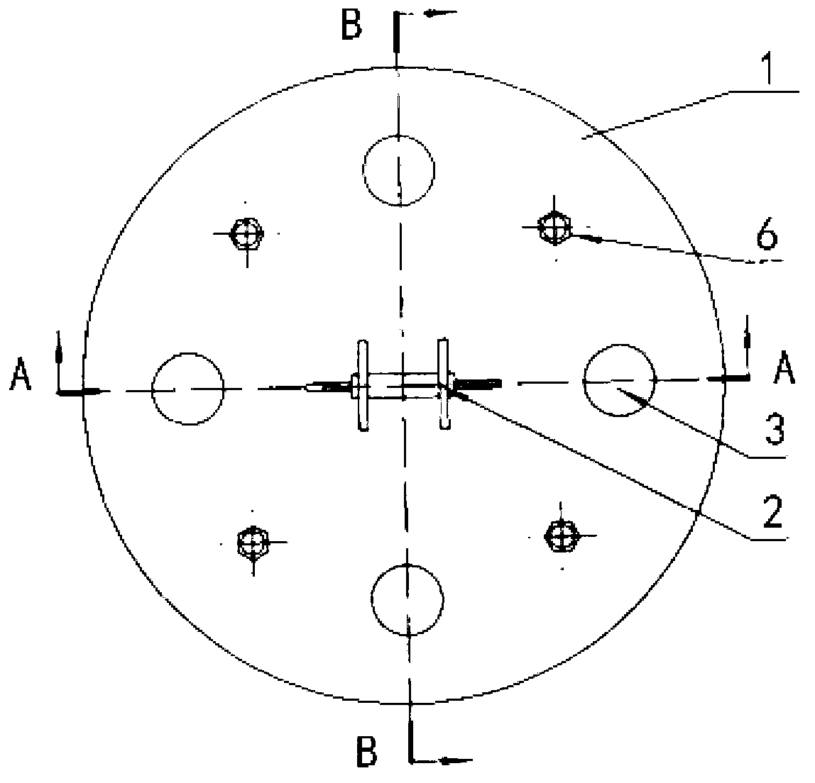
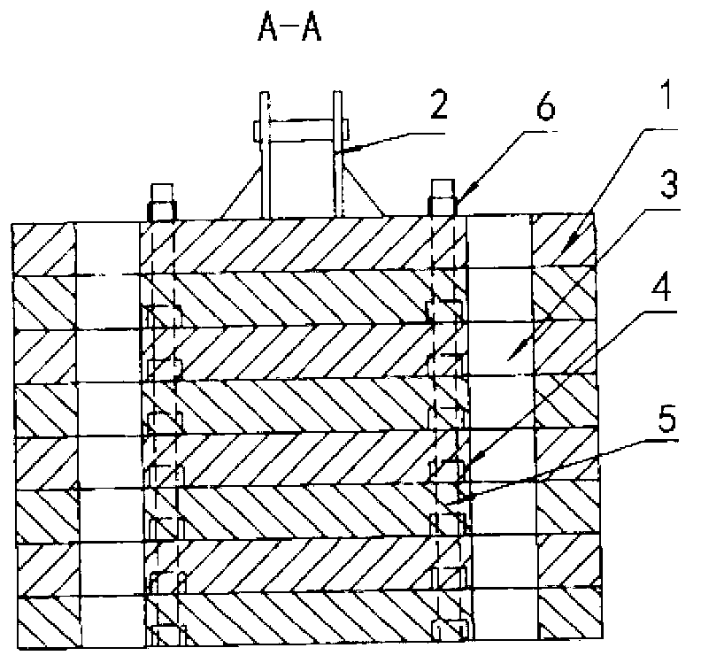
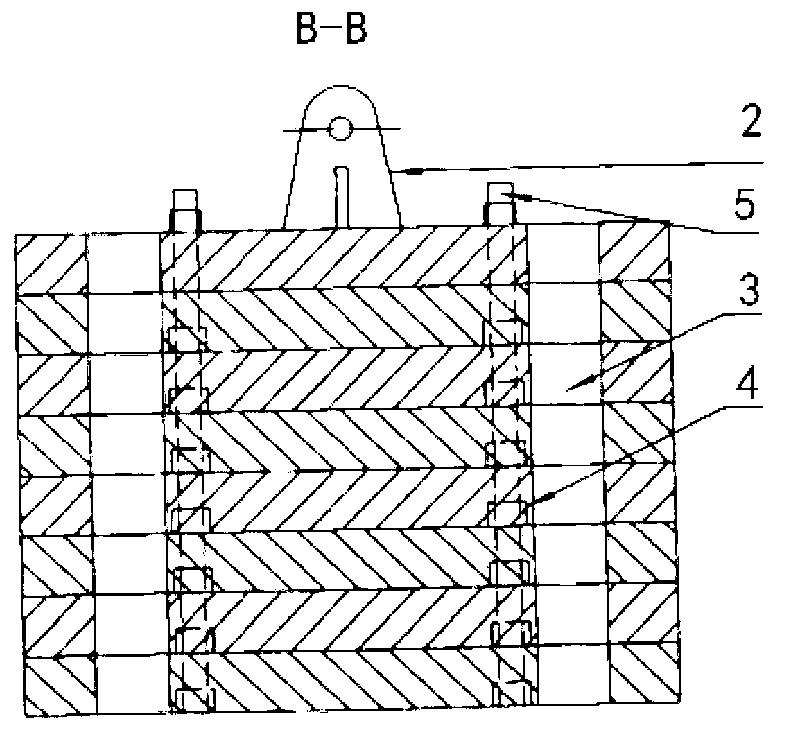
[0039] Such as Figure 4 , Figure 5 As shown, the shear resistant combination rammer provided by the present invention includes at least one first rammer body 7, each of the first rammer body 7 has the same structure, and is stacked up and down, and the top of the first rammer body 7 on the uppermost layer is provided with the first rammer body Two rammer bodies 8, each first rammer body 7 and the second rammer body 8 are connected as a whole by several connectin...


PUM


Abstract

The invention relates to an anti-shear combined rammer which is characterized by comprising at least one layer of first rammer bodies, wherein the first rammer bodies are vertically stacked, and a second rammer body is arranged at the top of the first rammer body on the uppermost layer. The first rammer body on the uppermost layer is connected with the second rammer body through a connecting bolt, and vertical through holes are formed in the first rammer bodies and the second rammer body. A lifting lug is arranged at the top of the second rammer body, bosses are arranged at the tops of the first rammer bodies and the second rammer body, and grooves are formed in the bottoms of the first rammer bodies and the second rammer body. The first rammer body the uppermost layer and the second rammer body, as well as every two adjacent first rammer bodies, are matched and assembled with each other through the bosses and the grooves. The anti-shear combined rammer can meet the demand of different levels of rammers in the current dynamic compaction construction and can avoid the problem that the connecting bolt is damaged by shear force as the center of gravity of the rammer is off-center. The anti-shear combined rammer has the advantages of simple replacement operation, low cist and convenience in transportation.

Description

technical field [0001] The invention relates to the field of engineering machinery, in particular to a shear-resistant combined rammer. Background technique [0002] The dynamic tamping machine uses the high impact energy generated by the high drop of the rammer to forcefully squeeze crushed stones, flakes, slag and other materials with better performance into the foundation, forming one by one granular pier in the foundation, forming a composite between the pier and the pier. Foundation, to increase the bearing capacity of the foundation and reduce the settlement of the equipment. The uncoupling device is a tamper uncoupling device used on a dynamic compaction machine. The rammer is used to improve the bearing capacity of the deep foundation and is a weight block that is resistant to falling. [0003] During the process of dynamic compaction to strengthen the foundation, after the dynamic compaction machine lifts the rammer (not less than 20 tons) to a high place, the ram...

Claims


Application Information

Patent Timeline
IPC IPC(8): E02D3/054E02D3/08
Inventor 周波赵波柯春林
Owner XCMG CONSTR MACHINERY
Why Eureka
Try Eureka