Connection device for composite nodes and assembly method of connection device
A technology of composite materials and connection devices, which is applied in the direction of architecture and building construction, can solve the problems of increasing structural complexity and restricting applications, and achieve the effects of avoiding one-time dead connection, improving lightning protection level, and regular structure
- Summary
- Abstract
- Description
- Claims
- Application Information
AI Technical Summary
Problems solved by technology
Method used
Image
Examples
example 1
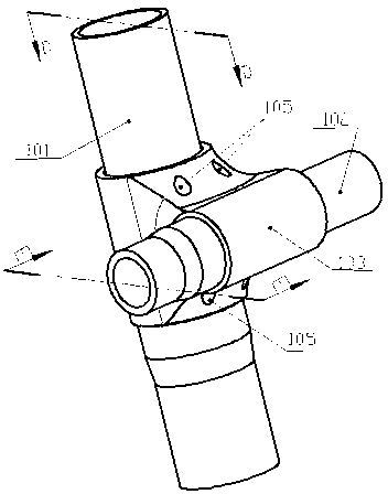
[0085] Such as Picture 11 As shown, the assembly process is schematic. First put the locking element assembly 104 into the single-ear hoop structure 103 in the axial direction P1 of the hoop main sleeve, and then insert the composite material auxiliary rod 102 along the hoop auxiliary rod sleeve axial direction P2. Until it reaches the position of the positioning table, loosen the tension bolt 1043 of the locking piece assembly 104 to increase the distance of the center seam in the locking block assembly by 5mm to 8mm, approaching the direction of the arc surface of the composite main rod 101, Insert the composite material main rod 101 to the positioning platform in the direction of P3, and pull the locking blocks 1041 and 1042 by tightening the nut 1044 to expand and compress the composite material main rod 101 and the composite auxiliary rod 102 to realize the integral connection.
example 2
[0087] Such as Figure 18 As shown, the full-composite node connecting device is a double-ear hoop structure, which includes a composite material main rod 101 and a composite material auxiliary rod 102 that are connected, and a connecting structure is formed by the double-ear hoop structure 106 connecting the nodes. The locking block 104 realizes a fixed connection. The outer surface of the joint is regular and there is no exposed connecting piece; especially, no metal material connecting piece is exposed.
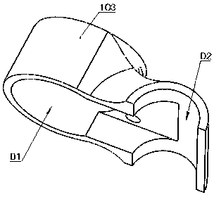
[0088] First put the two locking element assembly 104 into the binaural hoop structure 106 according to the directions P1 and P2 of the main sleeve D1 of the binaural hoop, and then place the composite material main rod 101 along the binaural hoop Insert with the main sleeve in the P3 direction until it reaches the position of the positioning table. Loosen the tension bolt 1043 of the locking piece assembly 104 to increase the distance between the two locking block assemblie...
PUM
 Abstract
Description
Claims
Application Information
 - R&D
- Intellectual Property
- Life Sciences
- Materials
- Tech Scout
- Unparalleled Data Quality
- Higher Quality Content
- 60% Fewer Hallucinations
Browse by: Latest US Patents, China's latest patents, Technical Efficacy Thesaurus, Application Domain, Technology Topic, Popular Technical Reports.
© 2025 PatSnap. All rights reserved.Legal|Privacy policy|Modern Slavery Act Transparency Statement|Sitemap|About US| Contact US: help@patsnap.com


