Connector, connector assembly and assembling method therefor
A connector, connecting to technology, applied in the parts of the connecting device, connecting/disconnecting, connecting and other directions of the connecting device, can solve the problems of the reduction of the elastic force of the locking arm, the lack of reliability of the strength of the locking arm, etc.
- Summary
- Abstract
- Description
- Claims
- Application Information
AI Technical Summary
Problems solved by technology
Method used
Image
Examples
no. 1 example
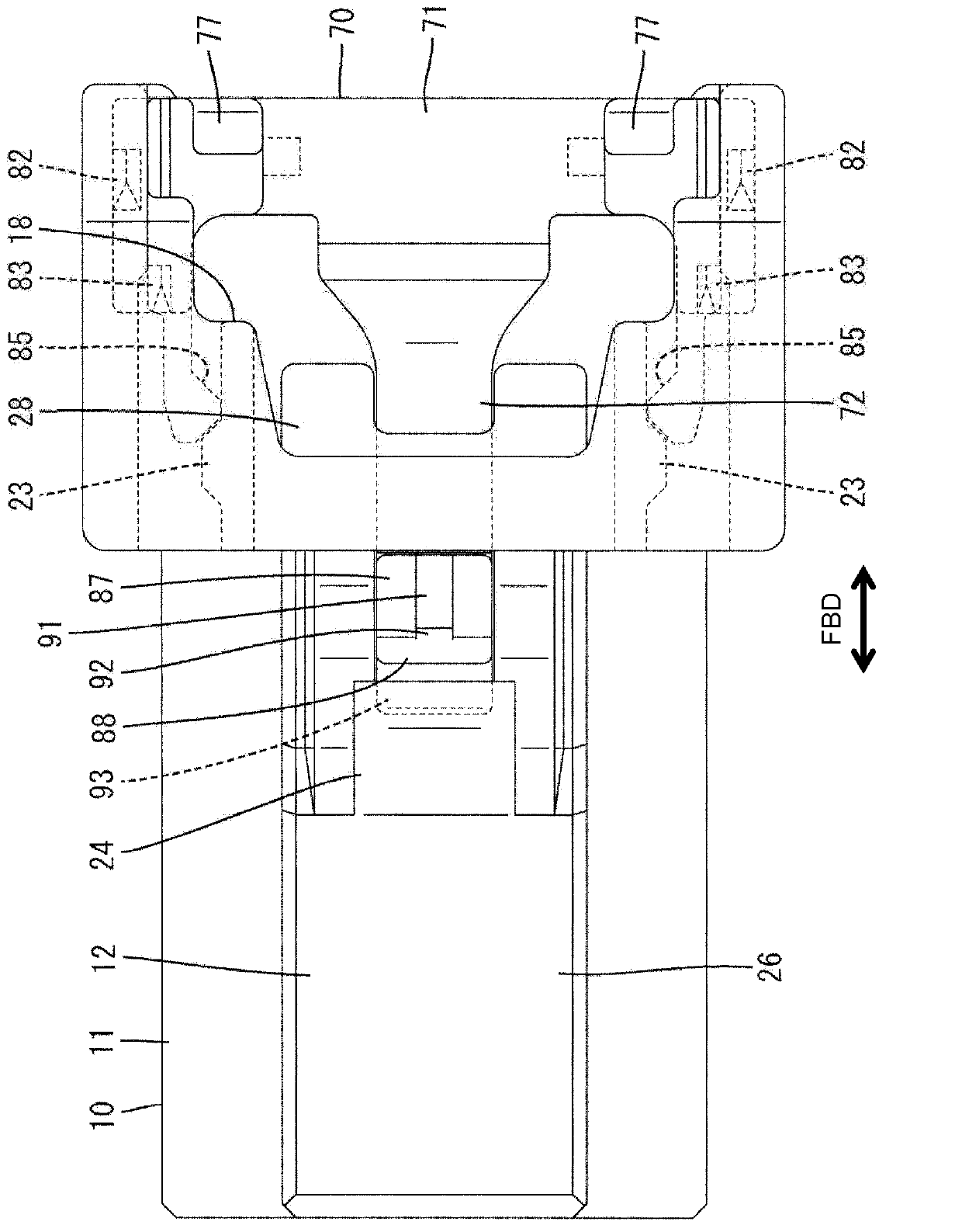
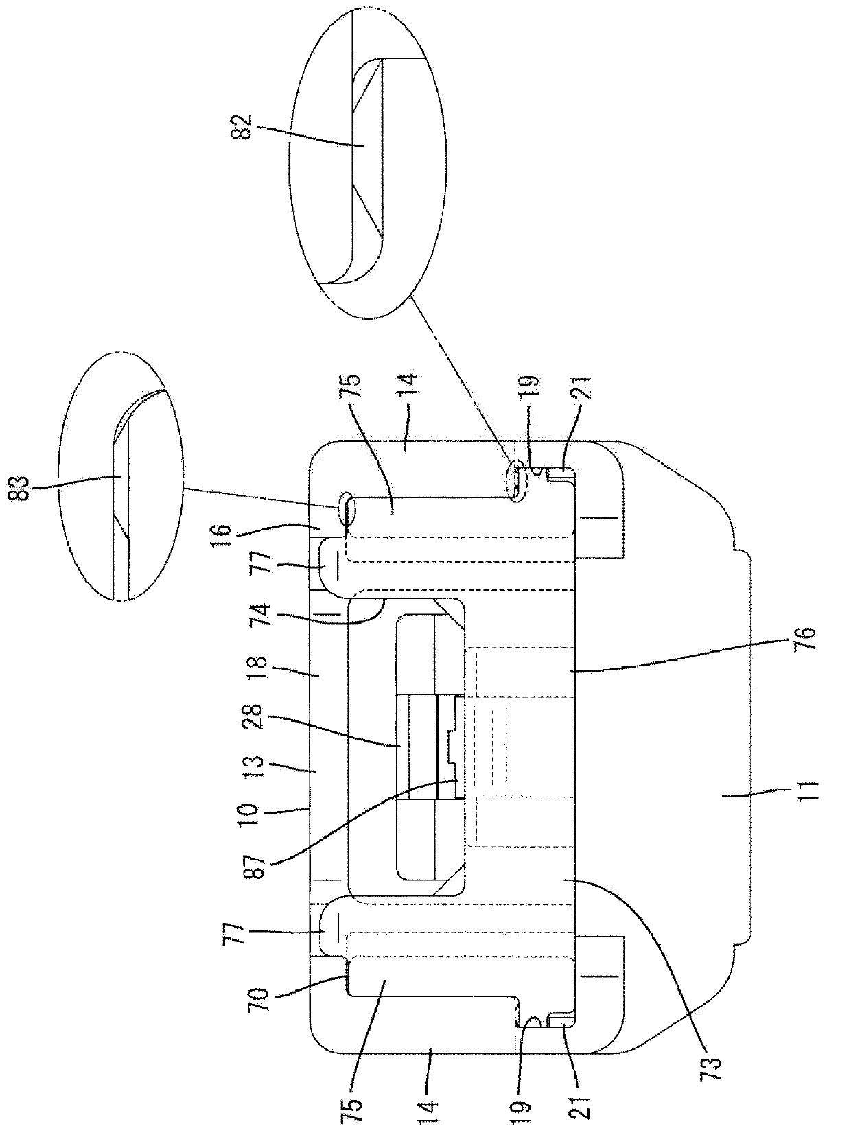
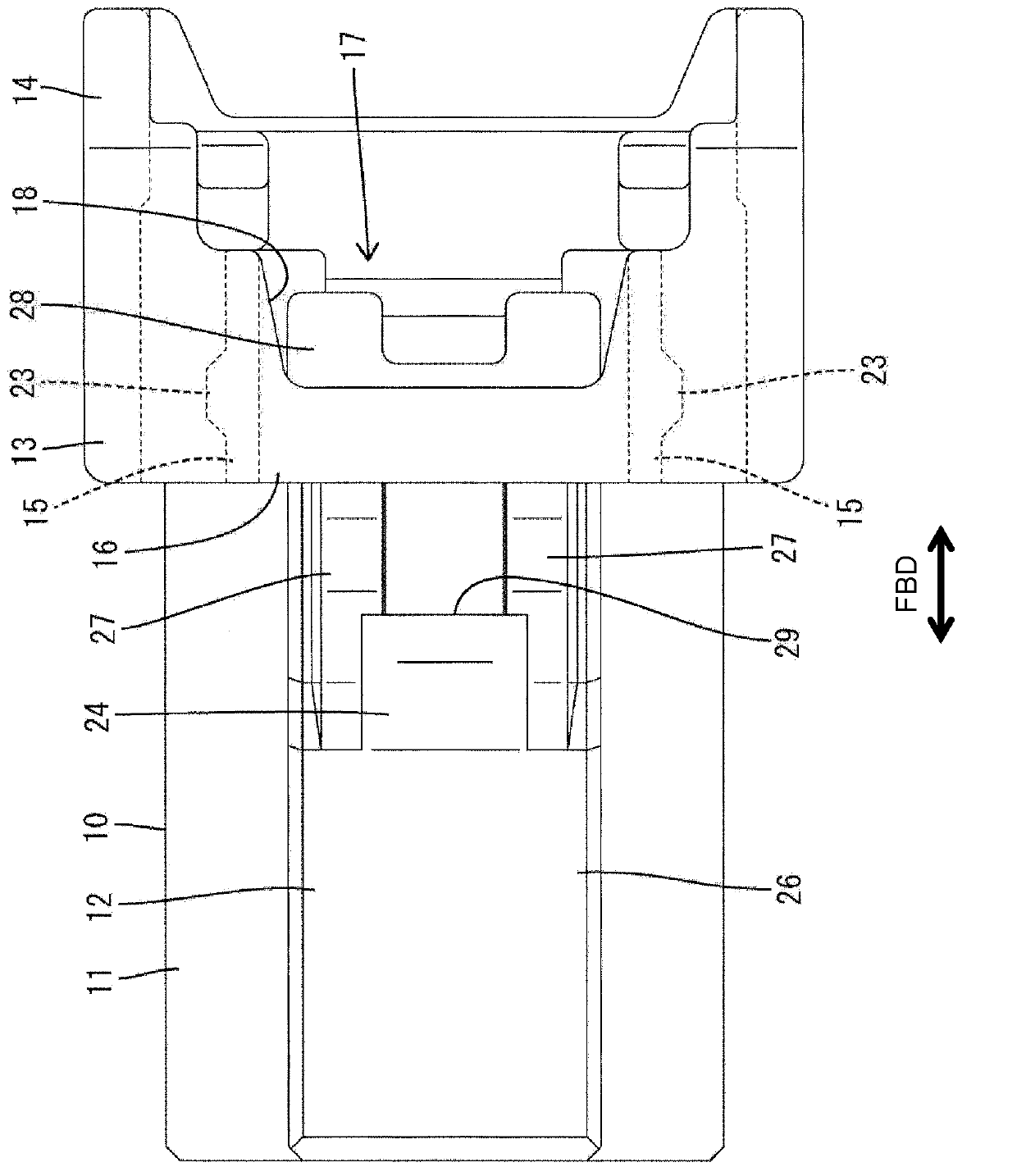
[0100] combine Figure 1 to Figure 20 A specific embodiment of the present invention is described. The connector A according to this embodiment includes a housing 10 and a mating housing 50 connectable to each other and a detection member 70 mounted on or in the housing 10 . Note that, in the following description, the side to be connected of the two housings 10 , 50 is referred to as the front side in terms of the front-rear direction FBD.
[0101] The fitting housing 50 is made of, for example, synthetic resin, and includes such as Figure 11 A forwardly open (in particular, substantially cylindrical) base 51 is shown in FIG. The lock receiving portion 52 is formed in or on the base 51 (specifically, the outer wall or the front end portion of the upper wall of the base 51 ). The lock receiving portion 52 penetrates through the base 51 (specifically, the upper wall) in the height direction HD (the direction intersecting the connection direction CD of the two housings 10 , ...
no. 2 example
[0153] Next, refer to Figures 21 to 27 A second specific embodiment of the present invention is described. In the connector B of this second embodiment, the configuration of the detection member 100 is partly different from the configuration of the detection member 70 of the first embodiment described above. Since other components are substantially the same or similar to those in the first embodiment, the same or similar components are denoted by the same reference numerals, and their structures, functions, and effects are not described.
[0154] as in Figure 24 to Figure 27 As shown in , a protrusion 102 (specifically in the form of a substantially rectangular block) is formed upward or outward on or near the front or distal end portion of the elastic arm portion 101 forming part of the detection member 100, for example, made of synthetic resin. Protrusion, the shape of the protrusion 102 is partly different from the protrusion 87 of the first embodiment. An auxiliary pr...
no. 3 example
[0167] Next, refer to Figure 28 A third specific embodiment of the present invention will be described. In the connector C of this third embodiment, the configuration of the auxiliary recess 35 is partly different from the auxiliary recess 32 formed on the inner upper surface of the receiving recess 31 of the lock arm 12 in the connector B of the second embodiment described above. structure. Since other components are substantially the same or similar to those in the first embodiment, the same or similar components are denoted by the same reference numerals, and their structures, functions, and effects are not described again.
[0168] The rear end portion of the receiving recess 35 of the third embodiment is chamfered to form at least one escape portion 36 opened inwardly or downwardly and rearwardly. By forming the escape portion 36 , the interference of the auxiliary protrusion 103 with the rear end portion of the lower surface of the locking protrusion 24 during the sli...
PUM
 Abstract
Description
Claims
Application Information
 - R&D
- Intellectual Property
- Life Sciences
- Materials
- Tech Scout
- Unparalleled Data Quality
- Higher Quality Content
- 60% Fewer Hallucinations
Browse by: Latest US Patents, China's latest patents, Technical Efficacy Thesaurus, Application Domain, Technology Topic, Popular Technical Reports.
© 2025 PatSnap. All rights reserved.Legal|Privacy policy|Modern Slavery Act Transparency Statement|Sitemap|About US| Contact US: help@patsnap.com


