Electronic lock

a technology of electronic locks and locks, applied in the field of electronic locks, can solve the problems of low reliability and complex structure of traditional electronic locks, and achieve the effect of simplifying the structure of locks and effective improving the reliability of locks

Inactive Publication Date: 2015-04-02
TRI STAR
View PDF10 Cites 6 Cited by
  • Summary
  • Abstract
  • Description
  • Claims
  • Application Information

AI Technical Summary

Benefits of technology

[0003]The present invention relates to an electronic lock which has a relook structure, for the above shortcomings. The present invention can effectively improve the reliability of the lock. Furthermore, the present invention simplifies the structure of the lock as well.

Problems solved by technology

The traditional electronic lock has a complex structure without high reliability.

Method used


Image

  • Electronic lock
  • Electronic lock
  • Electronic lock

Examples


Embodiment Construction

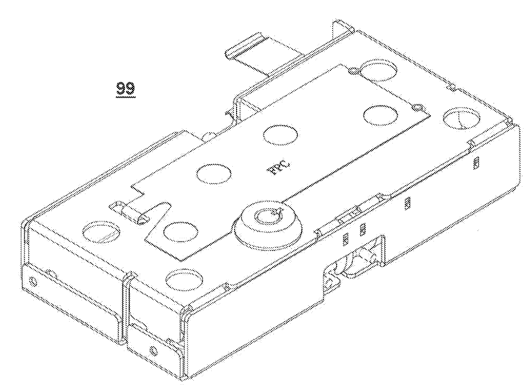
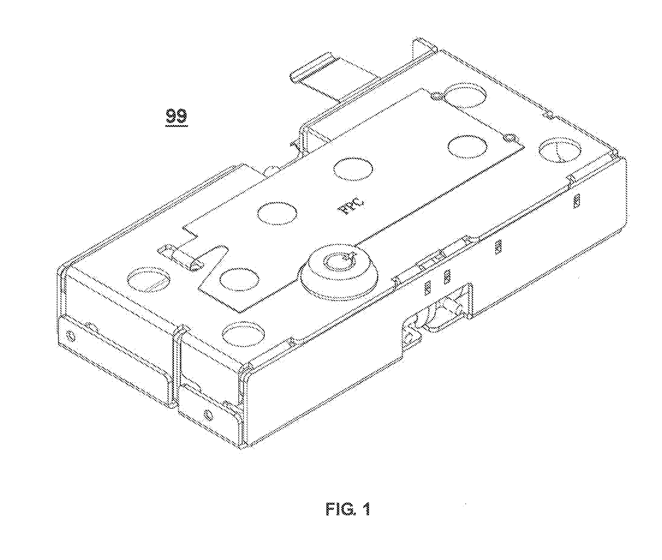
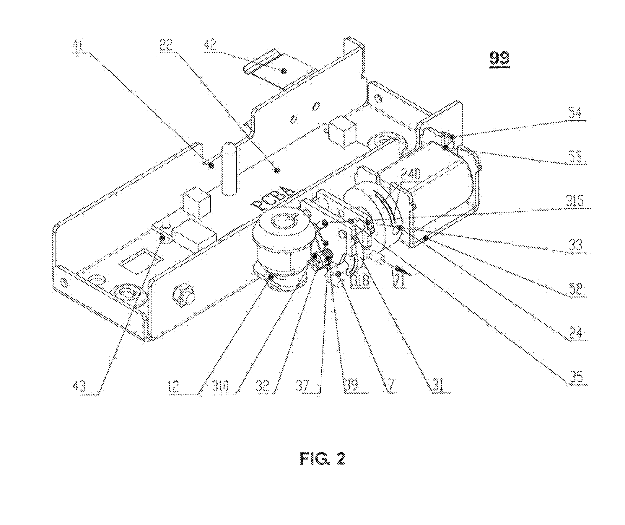
[0033]Figures non-restrictively disclose the technical means of the invention. The following will describe the invention technical solutions with the figures.

[0034]For FIG. 1-13, the marked elements are: 1, cam lock assembly; 11, cam Lock; 12, cam bolt; 13, toothed washers; 2, electronic control assembly; 21, PCB module; 22, membrane switch circuit; 23, electric motor; 24, drive disk; 25, Screws; 26, spring pin; 27, helicoidal disk; 3, latch bolt assembly; 31, latch bolt; 32, the second support sheet; 33, the first support sheet; 34, threaded sleeve; 35, double riveted column; 36, latch shaft; 37, torsion spring; 38, spring; 39, soft cord; 310, latch bolt mounting post; 311, the edge of latch bolt; 312, the left side of latch bolt; 313, the longer edge; 314 the shorter edge; 315, spring pin; 4, the electrical mounting assembly; 41, U-shaped bracket; 42, the battery snaps; 43, the mounting posts; 5, the mechanical mounting assembly; 51, U-shaped bracket; 52, the motor mounting bracke...


PUM


Abstract

This invention discloses an electronic lock, including cam lock assembly, electronic control assembly, lock latch assembly and latch bolt assembly. The latch bolt assembly includes latch bolt, latch bolt bracket and latch shaft. The latch bolt mentioned is pivoted at the latch bolt bracket, while latch shaft is translational positioned at it. By the latch shaft, cam bolt and electronic control assembly can connect with latch bolt and latch component in sequence. The latch shaft is configured with reset and compression spring, while latch bolt is with torsion spring and latch mounting parts, then the latch is able to linkage connect through latch mounting parts. From stated above, we can know the invention is ingeniously designed to lock/unlock latch parts, having lock assembly and electronic control assembly sharing one set of lock bolt (latch bolt). It can be seen that the invention effectively simplifies the existing lock structure.

Description

APPLICATION OF THE INVENTION[0001]In a first aspect of the present invention, the inventive electronic lock is intended to be mounted within the enclosure of a safe, a draw of a furniture and an office equipment such as, for example, a safe designed to store firearms, cash and passports. The inventive latch is a latch of general utility and may be used in any desired environment.BACKGROUND OF THE INVENTION[0002]The traditional electronic lock has a complex structure without high reliability.SUMMARY OF THE INVENTION[0003]The present invention relates to an electronic lock which has a relook structure, for the above shortcomings. The present invention can effectively improve the reliability of the lock. Furthermore, the present invention simplifies the structure of the lock as well.[0004]The present invention includes the following interrelated objects, aspects and features:[0005]The inventive electronic lock includes lock assembly, electronic control assembly, lock latch assembly and...

Claims


Application Information

Patent Timeline
Patent Type & Authority Applications(United States)
IPC IPC(8): E05B47/00E05C3/16
CPCE05B47/0001E05C3/16E05B47/0012E05B65/0075E05B2047/0086E05C3/24Y10T70/7102
Inventor CHEN, XI'ANLIU, JIAYANCHEN, WENKUN
Owner TRI STAR
Why Eureka
Try Eureka