Removal tool for transformer respirator

A technology for dismantling tools and respirators, applied in switchgear, electrical components, etc., can solve the problems of non-replacement of respirators, narrow operating space, etc., and achieve the effect of simple structure

Inactive Publication Date: 2013-09-18
STATE GRID CORP OF CHINA +2
View PDF4 Cites 6 Cited by
  • Summary
  • Abstract
  • Description
  • Claims
  • Application Information

AI Technical Summary

Problems solved by technology

[0004] At present, the transformer respirator is not replaced for a long time, and the oil bowl is fastened. Because the respirator is installed close to the transformer body, the operating space is narrow, and there is no suitable tool for disassembling the respirator.

Method used


Image

  • Removal tool for transformer respirator
  • Removal tool for transformer respirator

Examples


Embodiment Construction

[0013] The present invention will be further described in detail below in conjunction with the accompanying drawings and specific embodiments.

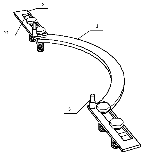
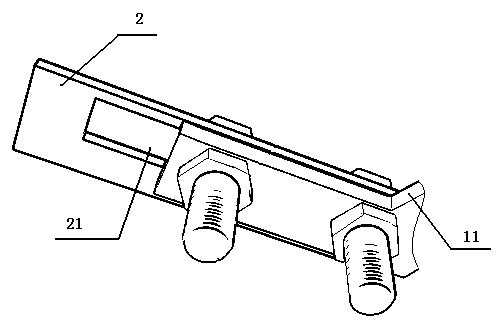
[0014] figure 1 The transformer respirator removal tool shown in the embodiment includes a bracket 1, a movable piece 2, and a positioning head 3; the bracket 1 is an arc-shaped plate structure with two symmetrical ends and two flat plates 11, and the movable piece 2 includes two, each Two movable pieces 2 are respectively fixed on the flat plate 11 at the end of the bracket 1 by means of bolts; the middle part of the movable piece 2 is provided with a long slotted hole 21, and two bolts passing through the long slotted hole 21 are fixed to the bolt holes on the flat plate 11. The nut at the end of the bolt is located below the flat plate 11; the upper surface of each movable piece 2 is fixedly provided with a positioning head 3; 3 have the same structure and are symmetrical to each other.

[0015] Furthermore, the bracket 1 describ...


PUM


Abstract

The invention discloses a removal tool for a transformer respirator and relates to a maintenance tool for electric power facilities. The removal tool for the transformer respirator comprises a frame, two movable pieces and two positioning heads; the frame with both ends symmetrical is provided with two flat plates and is of an arc plate structure; each movable piece is fixed on the flat plate at the end of the frame by means of bolts; a long slotted hole is arranged in the middle of the movable piece; two bolts passing through the long slotted hole are fixed to bolt holes on the flat plates; nuts at the end of the bolts are positioned below the flat plates; each positioning head of a ladder shaft structure is fixed on the upper surface of each movable piece; and the two positioning heads located on the two movable pieces are of the same structure and are symmetrical. The removal tool for the transformer respirator has the advantages that an oil seal bowl of the transformer respirator can be quickly removed, the structure of the removal tool is simple, and removal operation can be completed within a small space with no damage produced to the respirator.

Description

technical field [0001] The invention relates to a power facility maintenance tool. Background technique [0002] A large number of transformers are installed in the power supply and distribution systems of various manufacturing enterprises at home and abroad, which are mainly used to provide electric energy for production equipment and various auxiliary equipment. The transformer is mainly composed of coils, high and low voltage bushings, oil tanks, oil pillows, respirators and other components. [0003] The breather is the main part of the transformer. It is connected to the oil conservator through the pipeline to communicate with the atmosphere and the inside of the transformer oil tank. The respirator is equipped with color-changing silica gel to absorb moisture in the air and prevent moisture from entering the transformer oil tank to reduce the insulation level of the insulating oil. The respirator is a cylindrical structure, the top is connected to the oil pillow thro...

Claims


Application Information

Patent Timeline
Patent Type & Authority Applications(China)
IPC IPC(8): H02B3/00
Inventor 孙国才刘明辉宋巍
Owner STATE GRID CORP OF CHINA
Why Eureka
Try Eureka