Improved steel pipe piles and pipe pile structures

A technology for pipe piles and support structures, which is applied in infrastructure engineering, sheet pile walls, buildings, etc., and can solve the problems of coating damage, high initial cost, and expensive coating.

Inactive Publication Date: 2013-09-18
PILEPRO LLC
View PDF7 Cites 6 Cited by
  • Summary
  • Abstract
  • Description
  • Claims
  • Application Information

AI Technical Summary

Problems solved by technology

[0013] (1) It is relatively expensive to purchase and use such a large number of coatings;
[0014] (2) The coating is often damaged during transportation, leaving uncoated sc

Method used


Image

  • Improved steel pipe piles and pipe pile structures
  • Improved steel pipe piles and pipe pile structures
  • Improved steel pipe piles and pipe pile structures

Examples


Embodiment Construction

[0036] will now refer to the attached Figure 1 to Figure 11 Preferred embodiments of the present invention will be described.

[0037] The same elements in the various figures are indicated with the same reference numerals.

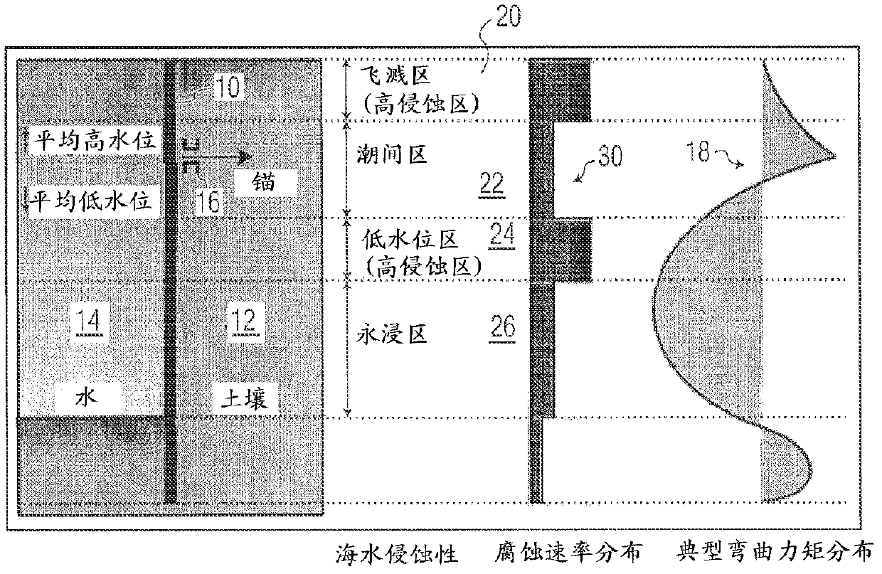
[0038] figure 1 A retaining wall 10 of steel pipe piles is shown, which retains soil 12 on one side and separates it from seawater 14 on the other side. As explained above in the Background of the Invention section, the pipe piles in the retaining wall are subjected to continuous stress due to the action of air and water, as well as continuous corrosion.

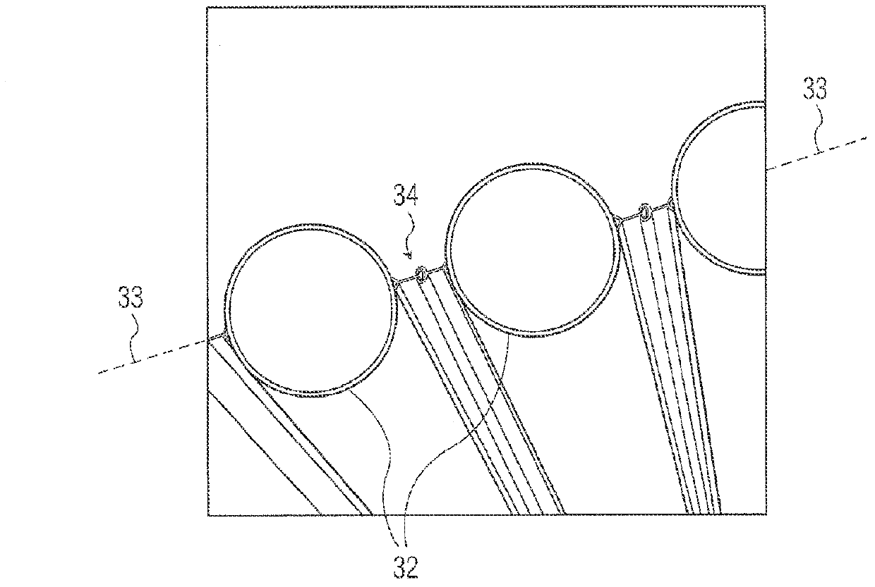
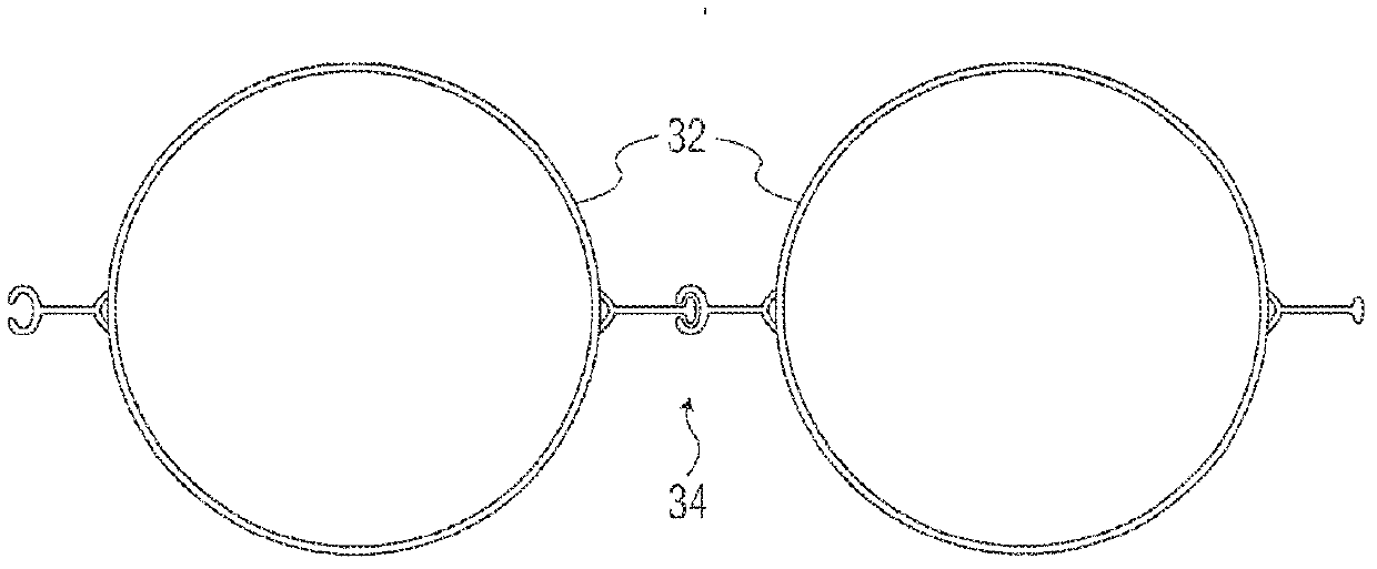
[0039] The tubular piles of the retaining wall are driven into the soil below the seabed with the longitudinal axes of the tubular piles arranged generally parallel and along a common generally horizontal line. figure 2 Shown is a series of pipe piles 32 arranged along a horizontal line 33 and connected together by intermediate connecting elements 34 secured by welding to the curved outer surfaces ...


PUM


Abstract

A pipe pile, for use in a foundation or a retaining wall, comprises a substantially cylindrical, and preferably steel, pipe body extending longitudinally between two opposite ends, the pipe body being' formed of a plurality of pipe sections, interlocked or welded together end-to-end and arranged on a common central longitudinal axis between the two ends, All of the pipe sections have substantially the same outside diameter; however, two or more pipe sections have differing inside diameters, and thus a differing wall thickness, between the two ends of the pipe pile.

Description

technical field [0001] The present invention relates to improvements in tubular piles, especially steel tubular piles, adapted to be driven into soil for use as structural elements in foundations or in walls. More specifically, the present invention relates to a metal pipe pile for use in foundations or walls which is corroded by the natural environment. Background technique [0002] Steel undergoes a natural corrosion process when it is in contact with water and at the same time present in air with oxygen. Material wear by corrosion depends on the one hand on local (eg hydrological) conditions and on the other hand the vertical position of the steel relative to the water level. When tubular piles are driven into the seabed, for example to support above-water or offshore platforms or to form seaside retaining walls, different vertical areas of the tubular piles experience different rates of corrosion or "rust". [0003] figure 1 Shown is a retaining wall 10 constructed of...

Claims


Application Information

Patent Timeline
IPC IPC(8): E02D5/28
CPCE02D5/285E02D5/06E02D31/06
Inventor 罗伯托·雷东多·文特
Owner PILEPRO LLC
Why Eureka
Try Eureka