Supercharge Your Innovation With Domain-Expert AI Agents!

Positioning bolt

A technology of positioning bolts and bolts, which is applied in the directions of engine components, mechanical equipment, valve devices, etc., can solve the problems of lax valve closing, low precision, over-position, etc., and achieve the effect of avoiding lax or over-positioning.

Inactive Publication Date: 2013-09-25
SUZHOU CITY JIANJUN TEXTILE MACHINERY PARTS FACTORY
View PDF0 Cites 0 Cited by
  • Summary
  • Abstract
  • Description
  • Claims
  • Application Information

AI Technical Summary

Problems solved by technology

However, in the process of use, often due to the large display error and low precision of the display device, the valve plate is not tightly closed or over-positioned in the valve body.

Method used


Image

  • Positioning bolt

Examples


Embodiment Construction

[0012] The present invention is described below in conjunction with accompanying drawing.

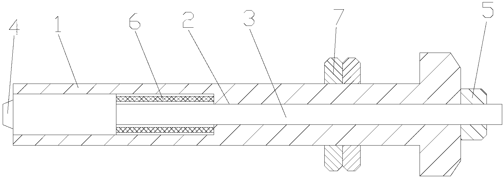
[0013] as attached figure 1 The shown positioning bolt of the present invention includes a bolt body 1, and a stepped hole 2 is opened in the bolt body 1; a thimble 3 matching the stepped hole 2 is provided in the stepped hole 2; The large-diameter end of the thimble 3 is flush with the tail end of the bolt body 1; the large-diameter end of the thimble 3 is provided with a boss 4; the boss 4 extends out of the bolt body 1; the small-diameter end of the thimble 3 Extend the head of the bolt body 1; the small diameter end of the thimble 3 is covered with an adjustment nut 5; the adjustment nut 5 is located outside the head of the bolt body 1 and is close to the head of the bolt body 1; the bolt body An elastic component is provided between 1 and the thimble 3; the elastic component is a spring 6; a self-locking nut 7 is also provided on the stem of the bolt body 1.

[0014] When the pos...


PUM


Abstract

The invention discloses a positioning bolt. The positioning bolt comprises a bolt body, and a stepped hole is formed in the bolt body; an ejector pin matched with the stepped hole is arranged inside the stepped hole; the major diameter end portion of the ejector pin is provided with a boss; the boss extends out of the bolt body; the minor diameter end of the ejector pin extends out of the head of the bolt body and is provided with an adjusting nut in a sleeve mode; the adjusting screw nut is arranged outside the head of the bolt body and abuts against the head of the bolt body; an elastic component is arranged between the bolt body and the ejector pin; the rod portion of the bolt body is further provided with a self-locking nut. According to the positioning bolt, whether a valve plate reaches limiting positions of opening or closing can be judged by observing a crack occurs between the adjusting nut and the head of the bolt body, and incomplete closing or position exceeding of a butterfly valve can be avoided.

Description

technical field [0001] The invention relates to a positioning bolt, in particular to a positioning bolt used in a manual butterfly valve. Background technique [0002] Most of the current manual butterfly valves use worm gear transmission. The torque on the hand wheel drives the valve shaft to rotate 0°~90° through the worm, the sector turbine, and through the key connection, so that the valve plate is in the open, closed or any position in between. Positioning bolts are arranged horizontally in the turbine box to limit the rotation angle of the turbine, and to adjust and fix the position of the valve plate when it is opened and closed. The opening and closing angle of the butterfly valve is displayed by the rotating pointer fixed on the valve shaft and the scale line engraved on the top surface of the transmission case cover. However, in the process of use, often due to the large display error and low precision of the display device, the valve plate is not tightly closed ...

Claims


Application Information

Patent Timeline
Patent Type & Authority Applications(China)
IPC IPC(8): F16K37/00
Inventor 翁杏根
Owner SUZHOU CITY JIANJUN TEXTILE MACHINERY PARTS FACTORY
Features
  • R&D
  • Intellectual Property
  • Life Sciences
  • Materials
  • Tech Scout
  • Unparalleled Data Quality
  • Higher Quality Content
  • 60% Fewer Hallucinations
Learn More