Camera assembly structure

a technology of camera and assembly structure, which is applied in the field of web cameras, can solve the problems of increasing the length of the clamping arms of the damper, the breakage of the electronic device, etc., and achieves the effect of facilitating the carrying and storage of the camera and reducing the overall siz

Inactive Publication Date: 2006-08-03
BEHAVIOR TECH COMPUTER
View PDF14 Cites 40 Cited by
  • Summary
  • Abstract
  • Description
  • Claims
  • Application Information

AI Technical Summary

Benefits of technology

[0004] The objective of the present invention is to provide an assembly structure that is fo

Problems solved by technology

Although the damper can be adjusted according to the thickness of the various electronic devices, a large clamping force can easily cause the electronic device to break.
Furthermore, the main drawback of the damper is that for those electronic devices with a greater thicknes

Method used


Image

  • Camera assembly structure
  • Camera assembly structure
  • Camera assembly structure

Examples


Embodiment Construction

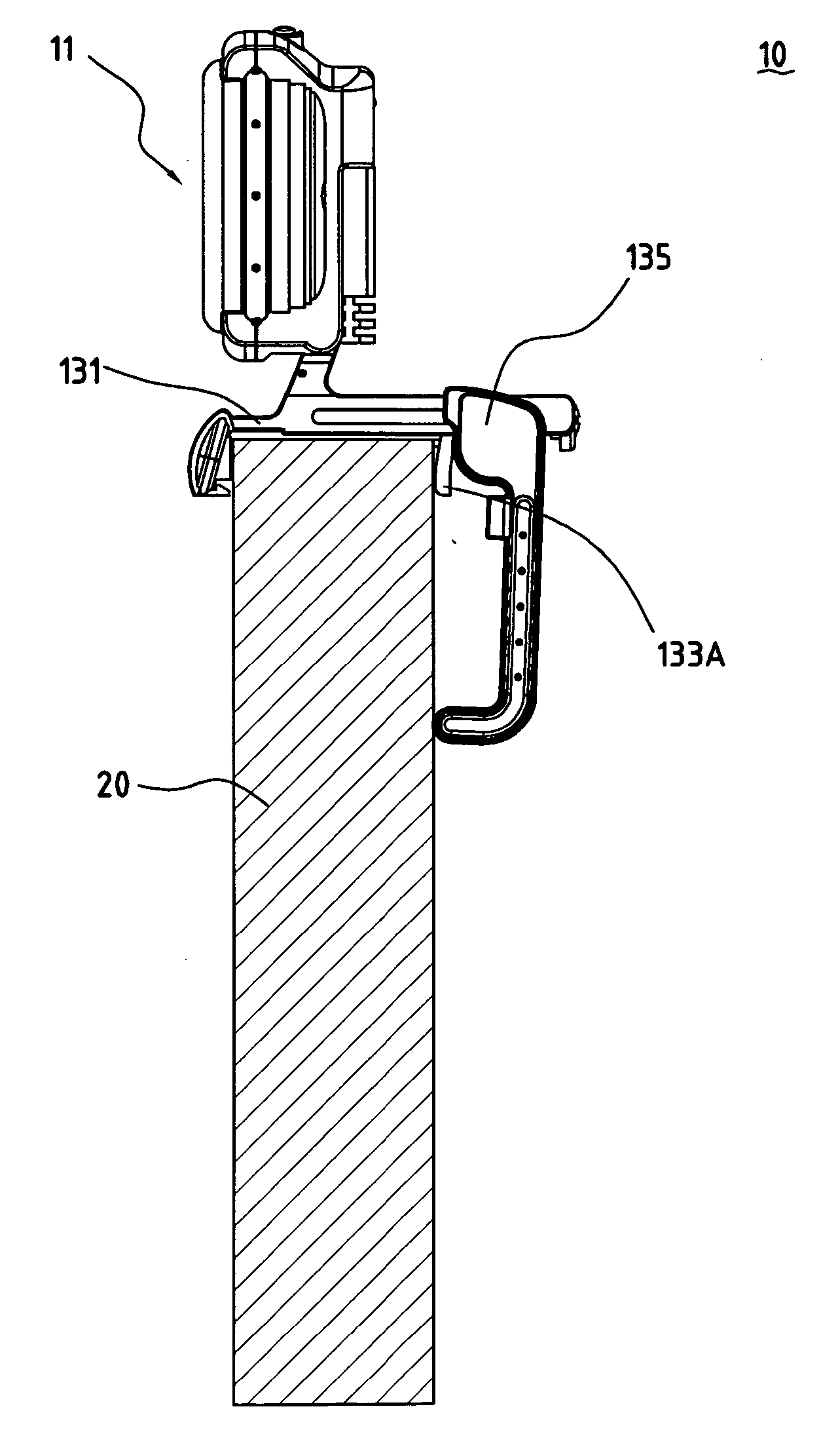
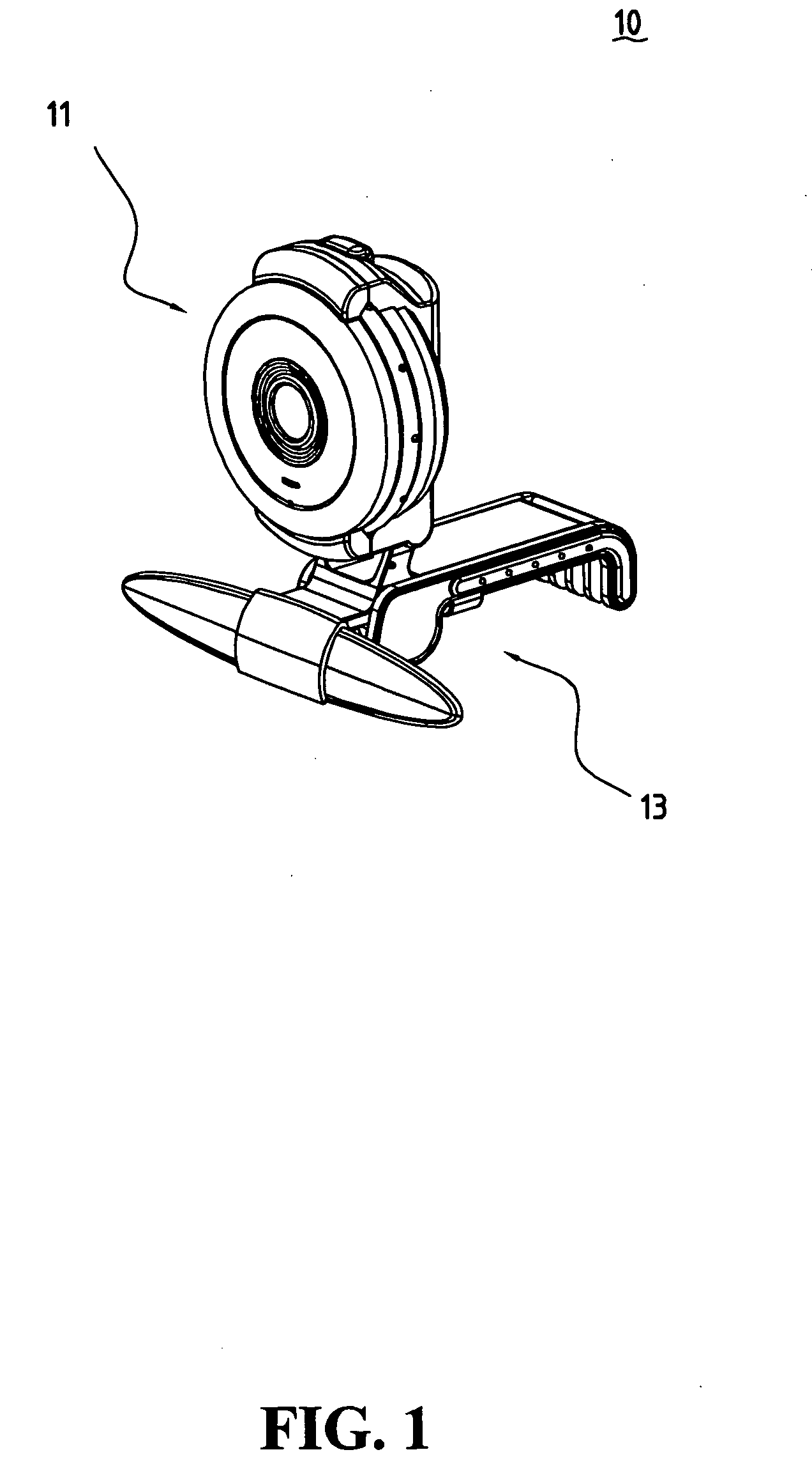
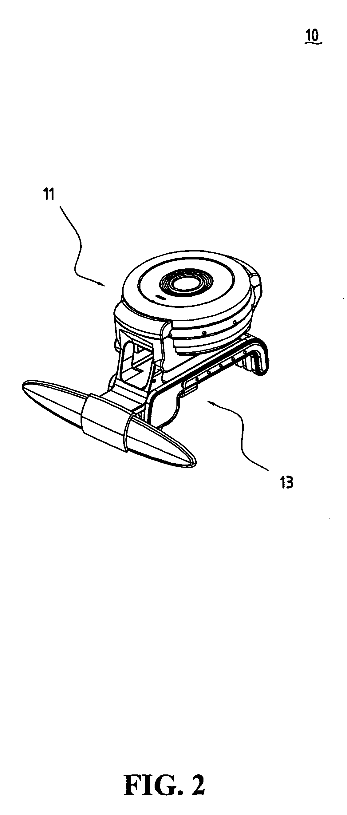
[0014]FIG. 1 shows an elevational diagram of the camera assembly structure of the present invention, while FIG. 2 shows a rotating positional diagram of the body of the present invention. The assembly structure 10 of the present invention is an assembly structure used for a camera. The camera can be a web cam, a digital cam, etc. The assembly structure 10 includes a body 11, and a base 13. The internal space of the body 11 can contain the optical module / circuit module 117 of the camera, and the body 11 is connected at the base 13 rotatable at any degree. When the body 11 rotates so as to be almost parallel to the base 13, the overall size of the assembly structure 10 can be significantly reduced to facilitate carrying and storage.

[0015]FIG. 3 shows an exploded diagram of the camera assembly structure of the present invention. The body 11 includes a front cover 111, a back cover 113, and a focus ring 115 clamped between the front cover 111 and the back cover 113. The shape of the bo...


PUM


Abstract

The present invention is a camera assembly structure having a body and a base. The body, having a front cover, a back cover and a focus ring clamped between the front and back covers, is connected at the base and can rotate in relation to the base. The base has a front base, an elastic component, and a back base. The front base has two side troughs for inserting the elastic component, and the elastic component can move along the side troughs. The back base engaging with partial structure of the front cover is connected at the elastic component and can use the elastic component as an axis so as to rotate downward.

Description

FIELD OF THE INVENTION [0001] The present invention is related to a web camera; particularly, it is related to a foldable web camera so as to reduce the overall size for carrying and storage, and for providing a clamping capability to clamp on an electronic device. BACKGROUND OF THE INVENTION [0002] The holding means for holding the conventional web cams on an electronic device, such as a notebook, an LCD, and so on, is as follows: One means is to adapt the clamping force of a damper so as to clamp the web cam on the electronic device. Although the damper can be adjusted according to the thickness of the various electronic devices, a large clamping force can easily cause the electronic device to break. Furthermore, the main drawback of the damper is that for those electronic devices with a greater thickness, the length of the two clamping arms of the damper must be increased. Another means is to adapt a base in slight n-shape so as to utilize the fixed size of the opening of the bas...

Claims


Application Information

Patent Timeline
IPC IPC(8): H04N5/225
CPCH04N5/2251H04N23/50
Inventor WU, CHIEH-FENG
Owner BEHAVIOR TECH COMPUTER
Why Eureka
Try Eureka