Rubber crawler

a crawler and rubber technology, applied in the field of rubber crawlers, can solve the problems of lowering the durability of the crawler, affecting so as to improve the safety of the crawler, and reduce the risk of fractur

Inactive Publication Date: 2005-08-04
SUMITOMO RUBBER IND LTD
View PDF7 Cites 40 Cited by
  • Summary
  • Abstract
  • Description
  • Claims
  • Application Information

AI Technical Summary

Benefits of technology

[0011] In this case, the crawler is increased not only in the torsional rigidity thereof but also in the endurance against stress acting in the widthwise direction of the crawler. Although the elastic member has a relatively small thickness at its portion where the widthwise reinforcing members are embedded, the inner circumferential joint portion may be spaced away from the thin portion because the inner circumferential joint portion is located near the center of the space between the widthwise reinforcing members. Thus, the inner circumferential joint portion may achieve an increased joining strength.
[0012] The joint portion on the outer circumferential surface of the crawler body may include a portion inclined at 10° or more and 60° or less relative to the widthwise direction of the crawler body as seen in plan viewed from the outer circumferential surface of the crawler. In this case, the stress may be adequately distributed along the longitudinal direction of the belt by defining the angle of inclination to be 10° or more. In the meantime, the angle of inclination defined to be 60° or less affords the ease of locating the joint in the ground non-engaging portion defining the area excluding the lugs.

Problems solved by technology

As described above, the rubber crawler having the endless belt shape has the following problem because of the inclusion of a joint at which the opposite ends of the rubber belt are joined together.
That is, the crawler sustains cracks originating from the joint and growing therefrom, so that the crawler suffers a serious damage which results in a lowered durability of the crawler.
Therefore, the joint on the outer circumferential surface of the crawler encounters a serious stress concentration because the joint is subjected to stress which is not distributed along the longitudinal direction of the belt.
Since the joint on a surface of such a lug or within such a lug is subjected to a greater stress associated with traction and the like, the joint is susceptible to interfacial separation and cracks.
In addition, the cracks grow to cause a serious damage to the crawler.
This results in the lowered durability of the crawler.

Method used


Image

  • Rubber crawler
  • Rubber crawler
  • Rubber crawler

Examples


first embodiment

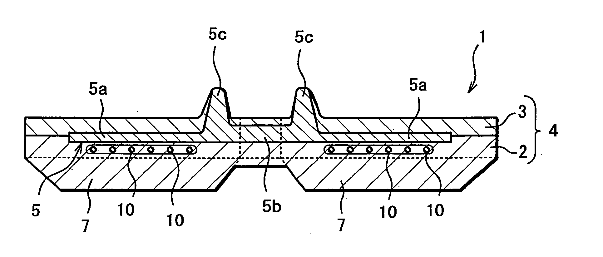
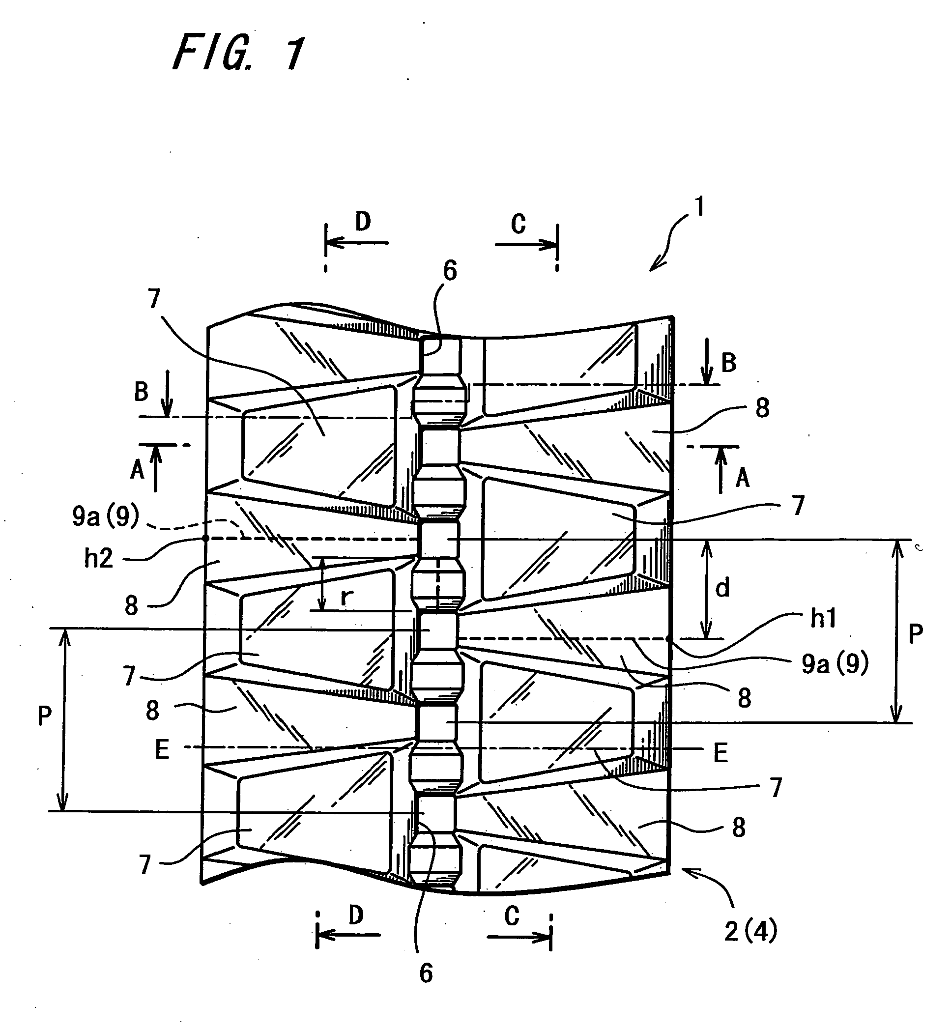
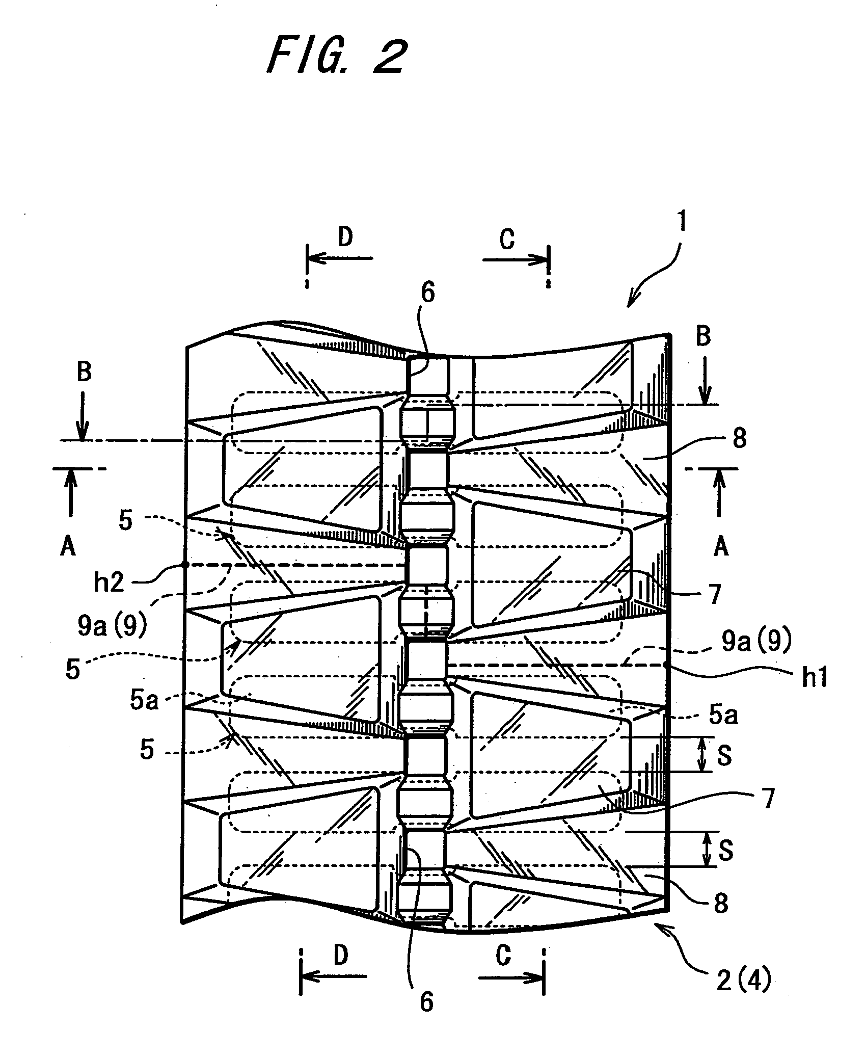
[0026]FIG. 1 is a plan view showing an outer circumferential surface (ground-engaging surface) of a rubber crawler 1 according to the invention. FIG. 2 is a plan view depicting core bars as a widthwise reinforcing member with broken lines which are added to FIG. 1. FIG. 3 is a plan view showing an inner circumferential surface of the rubber crawler 1. FIG. 4 is a sectional view taken on the line A-A in FIG. 1 through FIG. 3. FIG. 5 is a sectional view taken on the line B-B in FIG. 1 through FIG. 3. FIG. 6 is a sectional view taken on the line C-C in FIG. 1 through FIG. 3. FIG. 7 is a sectional view taken on the line D-D in FIG. 1 through FIG. 3.

[0027] As shown in FIG. 1 and FIG. 2, the rubber crawler 1 includes: lugs 7, as ground-engaging portions, projected at predetermined space intervals along a longitudinal direction of belt; and a ground non-engaging portion 8 defining an area excluding the lugs 7. The lugs 7 are separated into left-hand and right-hand lug groups via a portion ...

second embodiment

[0050]FIG. 8 is a plan view showing an outer circumferential surface (ground engaging surface) of a rubber crawler 20 according to the invention. In the rubber crawler 20, the left-hand and right-hand lugs 7 are arranged in substantially an inverted V-fashion or inclined relative to the widthwise direction of the crawler body 4. On the outer circumferential surface of the rubber crawler 20, the outer circumferential joint portion 9a located in the ground non-engaging portion 8 is also inclined at their lateral segments but for the portion near the widthwise center of the crawler body 4, the inclination of the segments being substantially in conformity with the layout of the lugs 7. On the other hand, the inner circumferential joint portion 9b located on the inner circumferential surface, which is the back side as seen in FIG. 8, is formed substantially in the straight line along the widthwise direction of the rubber crawler 20. In addition, the inner circumferential joint portion is...

third embodiment

[0051]FIG. 9 is a plan view showing an outer circumferential surface of a rubber crawler 30 according to the invention. The rubber crawler 30 has the same lug pattern as the rubber crawler 20, except for the layout of the outer circumferential joint portion 9a. That is, a difference between the rubber crawler 20 and the rubber crawler 30 consists in that the left-hand and right-hand segments of the outer circumferential joint portion 9a, as divided via the portion near the widthwise center of the crawler body 4, are at the longitudinal positions with respect to the longitudinal direction of the belt, which are defined in the opposite ways. It goes without saying that the rubber crawler 30 having such a construction provides the same working effects as the rubber crawler 20. In both of the rubber crawler 20 and the rubber crawler 30, the positions at the widthwise opposite ends h1, h2 of the outer circumferential joint portion 9a are shifted from each other along the longitudinal dir...


PUM


Abstract

The present invention relates to a rubber crawler including: a joint formed by joining together opposite ends of a crawler body comprising an elastic member shaped like a belt having the opposite ends; and lugs projected at predetermined space intervals along a longitudinal direction of the belt and arranged on an outer circumferential surface of the crawler body. The joint is disposed on the outer circumferential surface of the crawler body, as located in a ground non-engaging portion and at different positions with respect to the longitudinal direction of the belt, the ground non-engaging portion defining an area excluding the lugs. In this way, stress acting on the joint is distributed or reduced.

Description

FIELD OF THE INVENTION [0001] The present invention relates to an endless-belt rubber crawler for use in belted-track mobile apparatuses such as construction machines and agricultural machines. DESCRIPTION OF THE PRIOR ART [0002] The rubber crawler is used widely because it is more advantageous than an iron crawler in terms of lower noises, higher ride quality, better road-surface conservation characteristic and the like. While the rubber crawler includes a type wherein core bars are covered with rubber, a coreless type and the like, all those types are manufactured by forming rubber into an endless belt. Such an endless rubber belt may be formed by joining together opposite ends of a rubber belt cut in a certain length. As disclosed in Japanese Unexamined Patent Publication No. 2001-38818 (claim 1, FIG. 2), the joining of the opposite ends of the rubber belt is normally accomplished by curing an un-cured or semi-cured rubber belt with its opposite ends in butt connection. In some c...

Claims


Application Information

Patent Timeline
Patent Type & Authority Applications(United States)
IPC IPC(8): B62D55/253B62D55/24
CPCB62D55/24
Inventor UENO, YOSHIO
Owner SUMITOMO RUBBER IND LTD
Why Eureka
Try Eureka