Temperature-control flow-in-gap electric water heater

A hydroelectric and water heater technology, applied in fluid heaters, lighting and heating equipment, etc., can solve problems such as the inability to detect and control the temperature of water flow in real time

Inactive Publication Date: 2013-09-25
张秀英
View PDF10 Cites 0 Cited by
  • Summary
  • Abstract
  • Description
  • Claims
  • Application Information

AI Technical Summary

Problems solved by technology

However, the gap water flow electric heater disclosed in the above-mentioned patent is not equipped with a temperature control detection element, and cannot detect and regulate the temperature of the water flow in real time.

Method used


Image

  • Temperature-control flow-in-gap electric water heater
  • Temperature-control flow-in-gap electric water heater
  • Temperature-control flow-in-gap electric water heater

Examples


Embodiment Construction

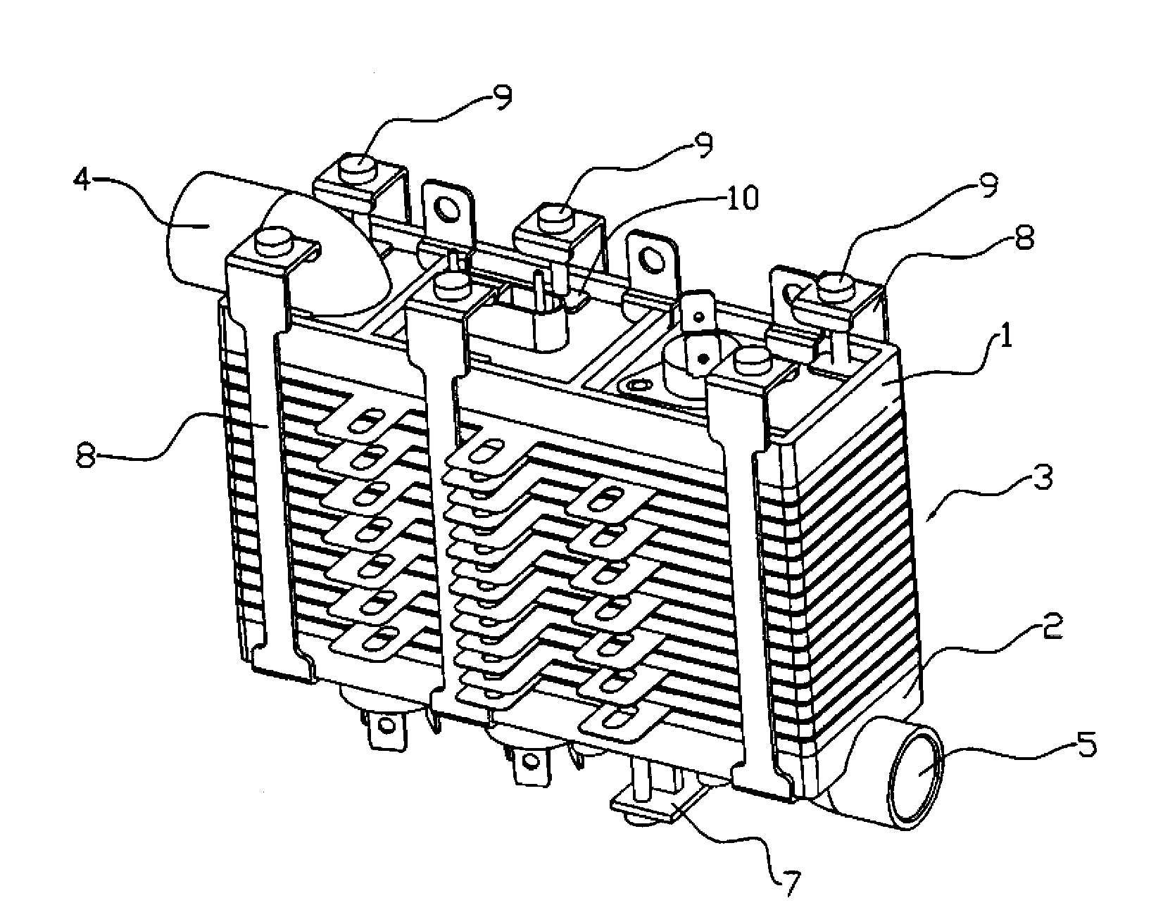
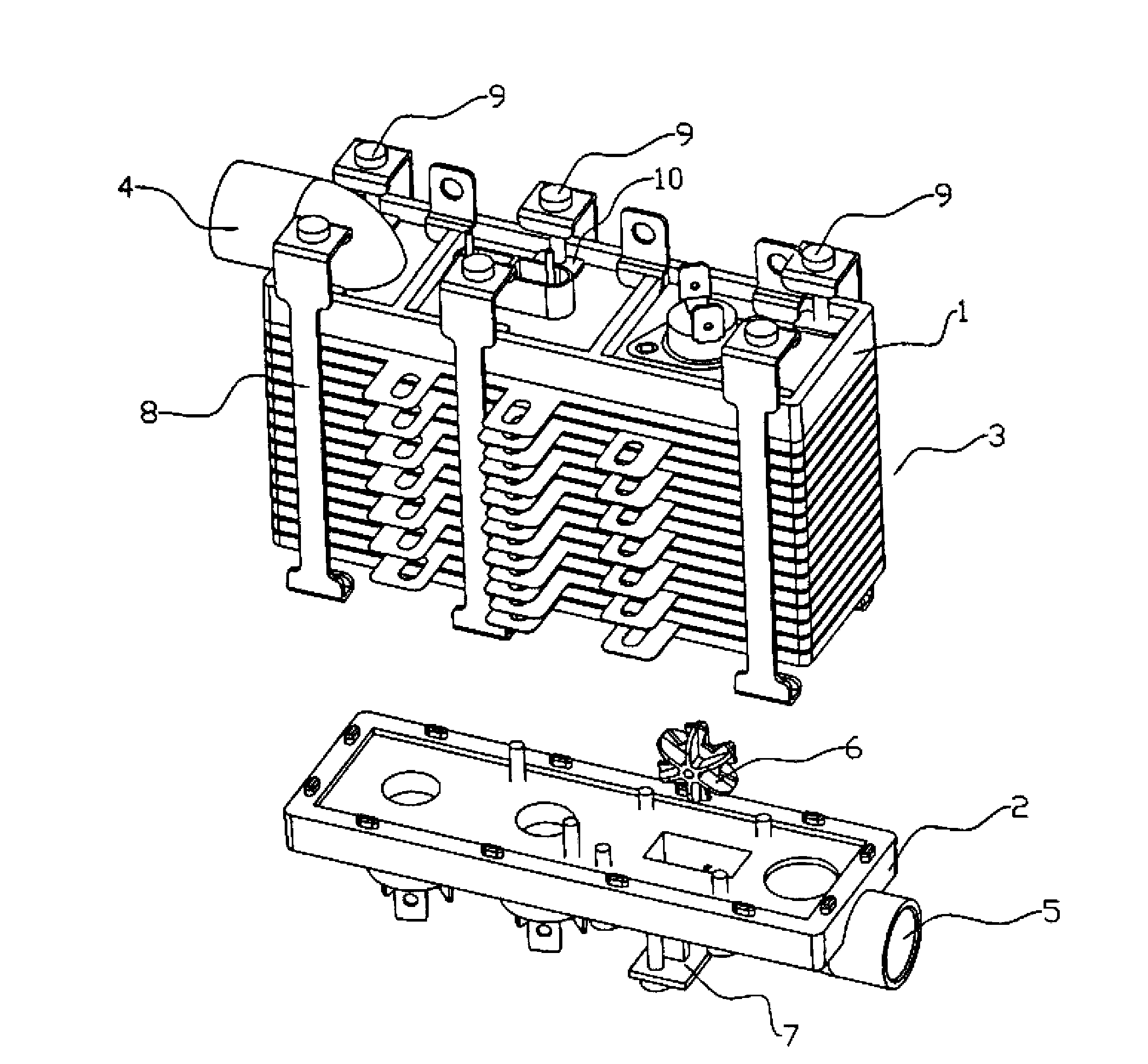
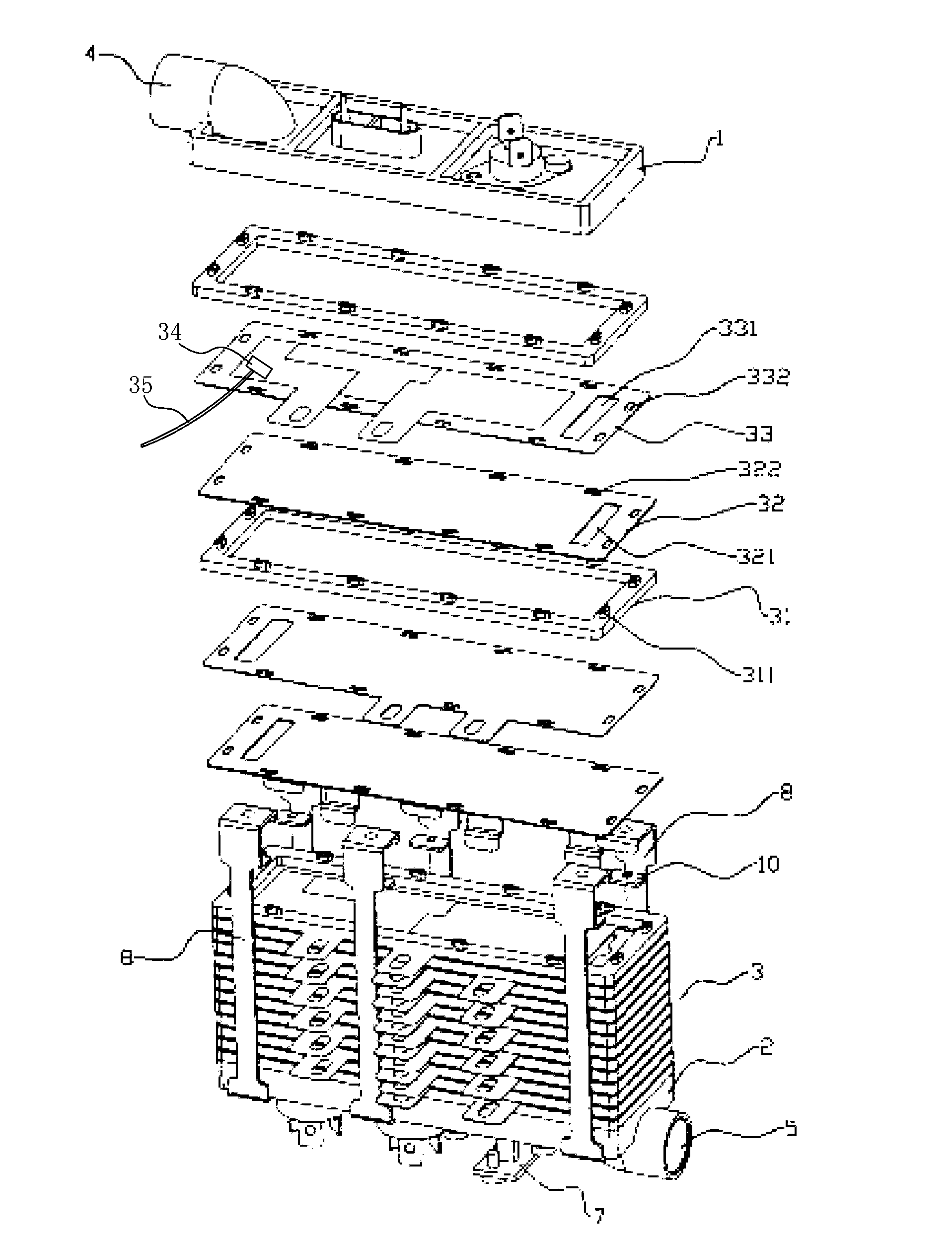
[0016] refer to Figure 1 to Figure 3 , the gap water flow electric water heater with temperature control provided by the present invention includes an upper base body 1, a lower base body 2, a gap water flow electric heating device 3 arranged between the upper base body 1 and the lower base body 2, and installed on the upper base body 1 The water outlet pipe 4, and the water inlet pipe 5 arranged at the bottom of the lower seat body 2. The output direction of the water inlet pipe 5 is provided with an impeller 6, and the two sides of the bottom of the lower base body 2 are provided with a photoelectric detection head 7 for measuring the rotational speed of the impeller 6. The gap water flow electric heating device 3 is formed by stacking several heating units, and the heating unit includes a connecting ring 31, on which a supporting piece 32 is installed, and a heating piece 33 is laid on the supporting piece 32, wherein, The heating sheet 33 is provided with a temperature s...


PUM


Abstract

The invention discloses a temperature-control flow-in-gap electric water heater comprising an upper base, a lower base and a flow-in-gap electric heating device disposed between the upper base and the lower base. The flow-in-gap electric heating device is formed by stacking a plurality of heating units. Each heating unit comprises a connecting ring, a mounting plate is mounted on the connecting ring, a heating plate is laid on the support plate, a temperature sensor plate is disposed on the heating plate, and the temperature sensor plate is connected with an IC processing chip through a signal transmission wire. The temperature sensor plates are disposed on the heating plates of the temperature-control flow-in-gap electric water heater; accordingly, temperature of water in the heater can be detected in real time, a user can know the temperature of heated water clearly, and conditions for controlling the heater are provided for the user.

Description

technical field [0001] The invention relates to an electric water heater, in particular to a gap water flow electric water heater with temperature control. Background technique [0002] Chinese invention patent 200820201008.4 - an electric water heater that prevents dry burning discloses a structure of a crevice water flow electric heater. The specific structure of the crevice water flow electric heater is: the crevice water flow electric heater is stacked by several heating units The heating unit includes a connecting ring, on which a supporting sheet is installed, and a heating sheet is laid on the supporting sheet, and first and second water holes which are connected to each other are respectively opened on the supporting sheet and the heating sheet, and connected to A number of protrusions are arranged on the ring, first and second installation holes corresponding to the protrusions are respectively opened on the support sheet and the heating sheet, fastening arms are re...

Claims


Application Information

Patent Timeline
IPC IPC(8): F24H9/20F24H9/18
Inventor 陈振圳
Owner 张秀英
Why Eureka
Try Eureka