Exposure device and method

A technology of exposure device and exposure position, which is applied in the direction of photolithography exposure device, microlithography exposure equipment, optics, etc., can solve problems such as affecting production capacity and long exposure process time, and achieve the effect of improving production capacity and saving time.

Active Publication Date: 2013-09-25
BEIJING BOE OPTOELECTRONCIS TECH CO LTD
View PDF11 Cites 6 Cited by
  • Summary
  • Abstract
  • Description
  • Claims
  • Application Information

AI Technical Summary

Problems solved by technology

[0004] In the above exposure process, the exposure of the circuit pattern and the exposure of the logo pattern are carried out separately, and the exposure of the logo pattern is to expose the logo pattern to each product on the substrate one by one, which will lead to the exposure process The time is too long, which seriously affects the production capacity

Method used


Image

  • Exposure device and method
  • Exposure device and method
  • Exposure device and method

Examples


Embodiment Construction

[0037] The technical solutions in the embodiments of the present invention will be clearly and completely described below in conjunction with the accompanying drawings in the embodiments of the present invention. Obviously, the described embodiments are only some, not all, embodiments of the present invention.

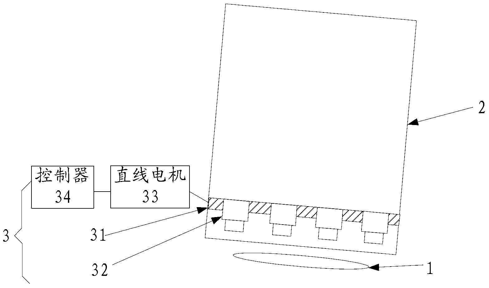
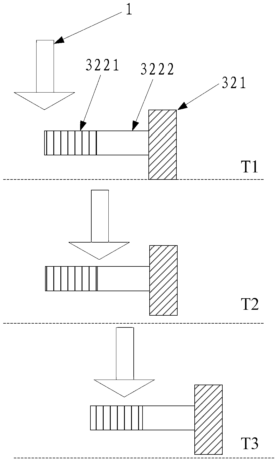
[0038] An embodiment of the present invention provides an exposure device, such as figure 1 As shown, the exposure device includes an exposure lamp 1, a mask plate 2 and a marking device 3, and the marking device 3 includes a rail frame 31, and the rail frame 31 is arranged on the mask plate 2; at least one A marking vehicle 32 , the marking vehicle 32 is arranged on the guide rail frame 31 . The controller 34 is used to control the guide rail frame 31 to move to the corresponding exposure position on the mask plate 2 before the exposure lamp 1, and control the marking vehicle 32 to move to the corresponding marking position, displaying Corresponding marking marks.

...


PUM


Abstract

The embodiment of the invention provides an exposure device and method, which relate to the technical field of display. The time of an exposure process can be saved, and the capacity is improved. The exposure device comprises an exposure lamp, a mask plate, marking equipment and a controller, wherein the marking equipment comprises a guide rail rack on the mask plate, and at least one marking trolley on the guide rail rack; the controller is used for controlling the guide rail rack to move to a corresponding exposure position on the mask plate prior to the exposure lamp and controlling the marking trolley to be positioned in a corresponding marking position so as to display a corresponding marking identifier.

Description

technical field [0001] The present invention relates to the field of display technology, in particular to an exposure device and an exposure method thereof. Background technique [0002] In the manufacturing process of array substrates, it is necessary to mark the manufactured products, that is, to make product identifications such as ID information and two-dimensional codes on the substrates, so that subsequent projects can realize computer automation and trace product status. [0003] When producing small-size (below 7inch) products, hundreds of products can generally be produced on one substrate of the 5th generation line. Usually after the exposure of the first-layer circuit pattern of each product is completed on the substrate, the marking equipment is used to expose the logo pattern of each product on the substrate one by one, and then develop, etch, peel off and other processes. Form the first layer of circuit pattern and logo pattern, and then realize the marking of...

Claims


Application Information

Patent Timeline
Patent Type & Authority Applications(China)
IPC IPC(8): G03F7/20
CPCG03F7/70541G03F7/70733G03F7/2045G03F7/70691G03F7/70716
Inventor 马海涛赵海生
Owner BEIJING BOE OPTOELECTRONCIS TECH CO LTD
Why Eureka
Try Eureka