Uplink power control method, network nodes and system

A network node and power control technology, applied in the field of communication, can solve problems such as insufficient uplink transmission power

Active Publication Date: 2013-09-25
GUANGDONG OPPO MOBILE TELECOMM CORP LTD
View PDF6 Cites 32 Cited by
  • Summary
  • Abstract
  • Description
  • Claims
  • Application Information

AI Technical Summary

Problems solved by technology

[0005] Embodiments of the present invention provide an uplink power control method, network node, and system, which can solve the problem that the UE's

Method used


Image

  • Uplink power control method, network nodes and system
  • Uplink power control method, network nodes and system
  • Uplink power control method, network nodes and system

Examples


Embodiment 1

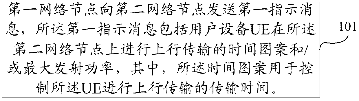
[0034] This embodiment provides an uplink power control method, such as figure 1 As shown, the method includes:

[0035] 101. The first network node sends a first indication message to the second network node, where the first indication message includes a time pattern and / or maximum transmit power for the user equipment UE to perform uplink transmission on the second network node, where: The time pattern is used to control the transmission time of the UE for uplink transmission.

[0036] Optionally, before the first network node sends the first indication message to the second network node, the method further includes: the first network node receives a second indication message sent by the UE, and the second network node The indication message is used to indicate that the uplink data buffered by the UE to be sent to the second network node exceeds a first predetermined threshold; the first network node determines that the UE performs uplink transmission on the second network node ...

Embodiment 2

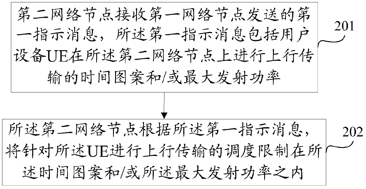
[0047] This embodiment provides an uplink power control method, such as figure 2 As shown, the method includes:

[0048] 201. A second network node receives a first indication message sent by a first network node, where the first indication message includes a time pattern and / or a maximum transmission power for user equipment UE to perform uplink transmission on the second network node.

[0049] 202. The second network node limits the scheduling of uplink transmission for the UE to within the time pattern and / or the maximum transmission power according to the first indication message.

[0050] Optionally, before the second network node receives the first indication message sent by the first network node, the method further includes: the second network node receives a second indication message sent by the UE, the first The second indication message is used to indicate that the uplink data buffered by the UE to be sent to the second network node exceeds a first predetermined threshold...

Embodiment 3

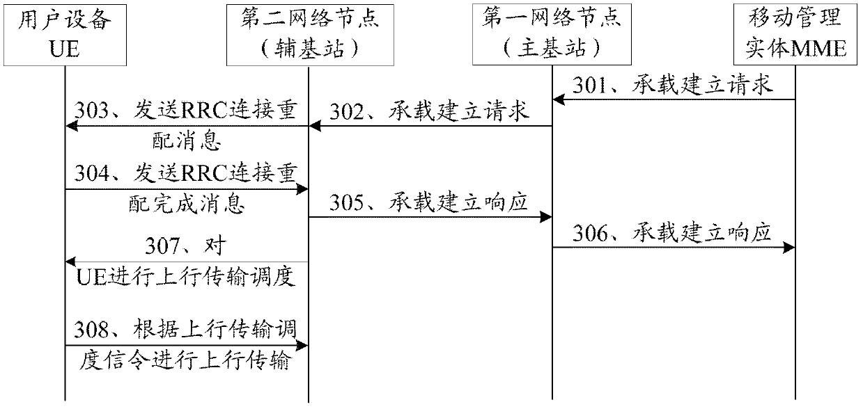
[0057] This embodiment provides an uplink power control method. The first network node is the primary base station, and the second network node is the secondary base station, such as image 3 As shown, the method includes:

[0058] 301. MME (Mobility Management Entity, mobility management entity) sends a bearer establishment request to a primary base station.

[0059] The bearer establishment request includes the UE corresponding to the bearer to be newly created and bearer service requirement information.

[0060] Optionally, the MME may also send a bearer deletion request or a bearer modification request to the primary base station.

[0061] 302. The primary base station determines the secondary base station to establish the new bearer, and sends a bearer establishment request to the secondary base station.

[0062] Specifically, after the primary base station receives the bearer establishment request, it decides which secondary base station should establish the radio bearer correspon...


PUM


Abstract

The invention discloses an uplink power control method, network nodes and a system, and relates to the communication technical field. The uplink power control method includes the steps that a first network node sends first indicating information to a second network node, wherein the first indicating information comprises time patterns and/or maximum launching power of UE for conducting uplink transmission on the second network node, and the time patterns are used for controlling transmission time of the UE for conducting uplink transmission. The uplink power control method, the network nodes and the system are suitable for controlling the uplink power of the UE in a carrier aggregation situation.

Description

Technical field [0001] The present invention relates to the field of communication technology, in particular to an uplink power control method, network node and system. Background technique [0002] In Release-10 (Version 10) of the 3GPP (3rd Generation Partnership Project) LTE (Long Term Evaluation) system, it supports CA (Carrier Aggregation) within a base station. Carrier aggregation is Multiple relatively narrowband carriers are aggregated into a wider frequency spectrum to meet the spectrum requirements of the LTE system. The CA inside a base station supports carrier aggregation of a maximum of 5 cells, that is, a UE (User Equipment) can simultaneously perform data transmission on a maximum of 5 cells. For a UE working in the CA state, its initial cell to access the system is PCell (Primary Cell), and then through the RRC (Radio Resource Control, radio resource control) reconfiguration process to add, modify or delete SCell (Secondary Cell, secondary cell), PCell can be ch...

Claims


Application Information

Patent Timeline
IPC IPC(8): H04W52/14
CPCH04W52/146H04W52/367H04W52/40H04W52/346H04W72/20
Inventor 曾清海黄曲芳
Owner GUANGDONG OPPO MOBILE TELECOMM CORP LTD
Why Eureka
Try Eureka