Loudspeakers and electronic equipment with loudspeakers
A loudspeaker and vibrating plate technology, applied in the field of loudspeakers, can solve the problems of sound quality degradation, inability to deepen and thin the loudspeaker, and the vibration plate is prone to split resonance, etc., to achieve stable frequency characteristics, excellent sound quality, and thinning effects.
- Summary
- Abstract
- Description
- Claims
- Application Information
AI Technical Summary
Problems solved by technology
Method used
Image


Examples
Embodiment approach 1
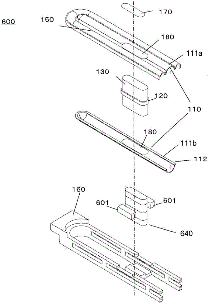
[0073] Embodiment 1 will be described below. First, the configuration of speaker 100 in this embodiment will be described. Figure 1A It is a top view of speaker 100 in this embodiment. and, Figure 1B is along Figure 1A A schematic cross-sectional view cut along the line AA' and viewed from the direction of the arrow a. and, Figure 1C is along Figure 1A A schematic cross-sectional view cut along line BB' in and viewed from the direction of arrow b.
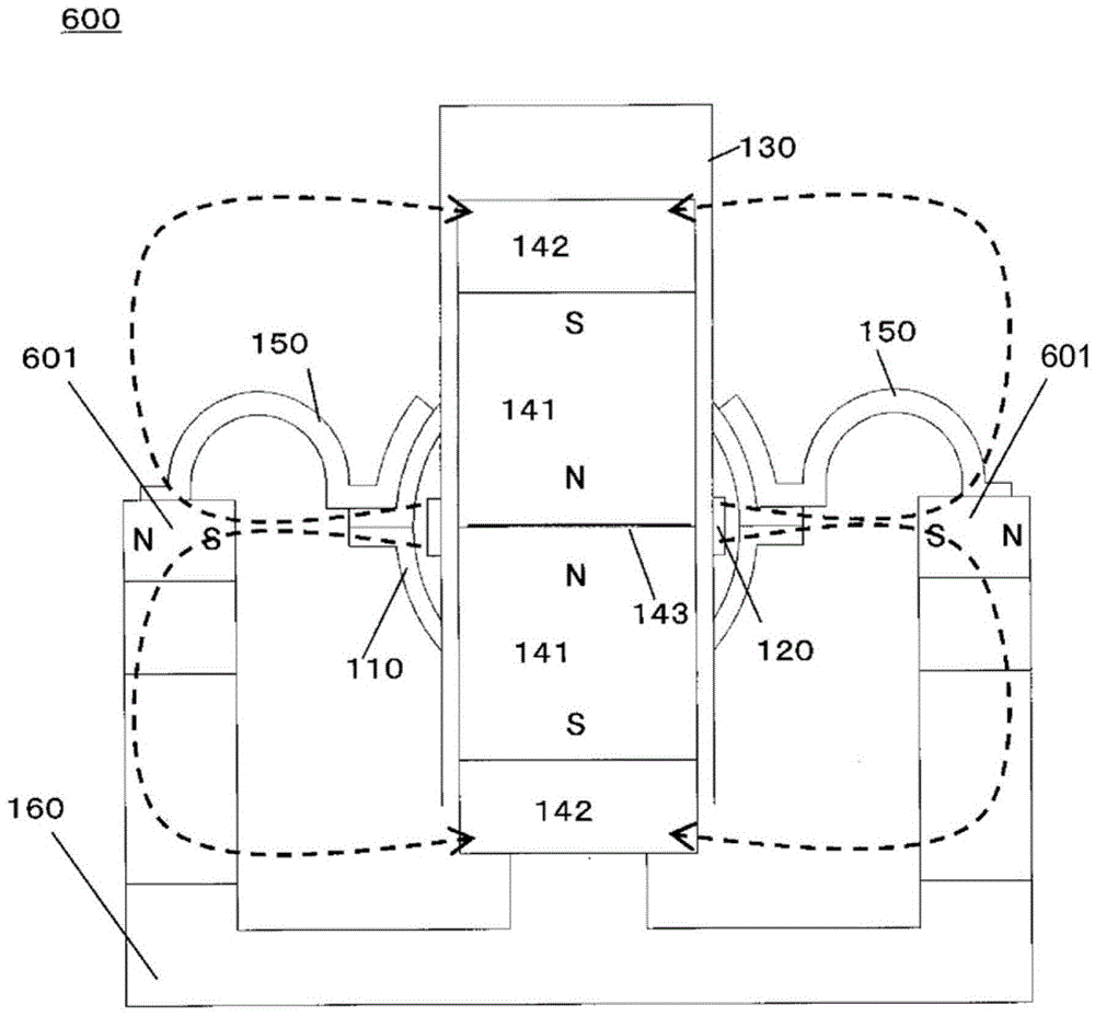
[0074] Speaker 100 is composed of diaphragm 110 , voice coil 120 , voice coil bobbin 130 , magnetic circuit 140 , edge portion 150 , frame 160 , and dustproof cover 170 . Such as Figure 1A As shown, the speaker 100 has an elongated shape with different vertical and horizontal lengths. Each structure of speaker 100 will be described below.
[0075] First, the vibrating plate 110 will be described. Figure 2A It is a plan view of the diaphragm 110, and only the left side of the line CC' in FIG. 1 is described. and, Fig...
Embodiment approach 2
[0128] Next, speaker 200 according to Embodiment 2 will be described. Speaker 200 other than speaker 100 of Embodiment 1 is characterized in that the lead-out wire of the voice coil is fastened inside diaphragm 110 .
[0129] Figure 9A is a plan view showing the speaker 200 . Figure 9B will be Figure 9A A schematic cross-sectional view cut along the longitudinal direction. in addition, Figure 9A and Figure 9B The vibration plate 111 a on the upper side of the vibration plate 110 is not shown. The grommet 201 is caulked to the end portion of the lower vibrating plate 111b in the longitudinal direction, and is integrally formed with the lower vibrating plate 111b. The wire 203 is fastened to the grommet 201 , and the other end of the wire 203 is connected to a terminal provided on a frame (not shown), and a signal for driving a speaker is inputted. As the wire 203, for example, a metal wire or the like can be used.
[0130] The voice coil 120 is fastened to the cent...
Embodiment approach 3
[0133] Next, Embodiment 3 will be described. Figure 10A It is a plan view of speaker 300 in this embodiment. and, Figure 10B is along Figure 10A A schematic cross-sectional view cut along the line G-G' in and viewed from the direction of the arrow g.
[0134] In addition to speaker 100 of Embodiment 1, speaker 300 uses diaphragm 210 having two through holes 180 in order to include two voice coil bobbins 130 , and fastens voice coil bobbin 130 through two through holes 180 .
[0135] Next, the driving position of the vibrating plate will be described. Consider the frequency band of the speaker to set the driver position. In speaker 1000 of conventional elongated structure and speaker 100 of Embodiment 1, one voice coil 1006 or voice coil 120 is arranged with the center of the longitudinal direction of diaphragm 1008 or 110 as a driving point. In the case of using the in-band diaphragm 1008 or 110 without resonance, that is, in the case of emphasizing reproduction of the...
PUM
 Abstract
Description
Claims
Application Information
 - R&D Engineer
- R&D Manager
- IP Professional
- Industry Leading Data Capabilities
- Powerful AI technology
- Patent DNA Extraction
Browse by: Latest US Patents, China's latest patents, Technical Efficacy Thesaurus, Application Domain, Technology Topic.
© 2024 PatSnap. All rights reserved.Legal|Privacy policy|Modern Slavery Act Transparency Statement|Sitemap