Bird repellent and anti-theft alarm device in orchards
An alarm device and anti-theft alarm technology, applied in anti-theft alarms, alarms, animal repellents, etc., can solve the problems of increasing the burden of equipment use and wasting resources.
- Summary
- Abstract
- Description
- Claims
- Application Information
AI Technical Summary
Problems solved by technology
Method used
Image

Examples
Embodiment Construction
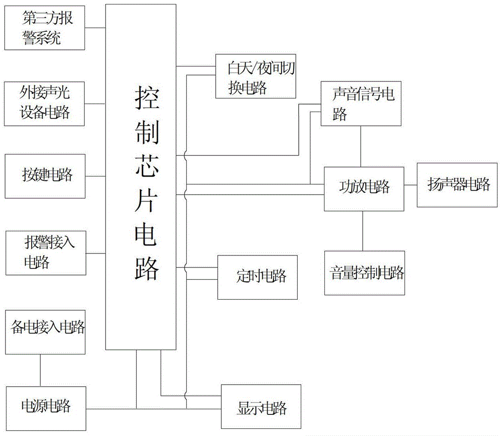
[0029] Such as figure 1 , figure 2 , Figure 4 and Figure 5As shown, an orchard bird repelling alarm device includes a power supply circuit and a control chip, the control chip is connected to the sound signal circuit, the sound signal circuit is connected to the first power amplifier circuit, and the first power amplifier circuit is externally connected to the speaker circuit , the control chip is connected with a day / night switching circuit, and the day / night switching circuit includes a triode Q1, the collector of the triode Q1 is connected to the control port P0 of the control chip through the first resistor R1 and powered by the power supply The port VCC1 is powered by a power supply circuit, the second resistor R2 is connected in series between the power port VCC1 and the triode collector, a photosensitive resistor and a capacitor are connected in parallel between the base of the triode Q1 and the ground, and the power port VCC1 and the triode base The third resisto...
PUM
 Abstract
Description
Claims
Application Information
PatSnap Eureka turns technology decisions into work you can execute. Powered by our Innovation Knowledge Graph, it runs expert workflows across engineering, life sciences, materials and intellectual property. Get your review-ready output in minutes.


