Light-emitting device and image sensor

An image sensor and light-emitting device technology, applied in the field of sensors, can solve the problems of inability to identify optical color-changing ink and holographic images, and the emission angle of the light-emitting device remains unchanged.

Active Publication Date: 2013-10-02
WEIHAI HUALING OPTO ELECTRONICS CO LTD
View PDF7 Cites 2 Cited by
  • Summary
  • Abstract
  • Description
  • Claims
  • Application Information

AI Technical Summary

Problems solved by technology

[0004] The present invention aims to provide a light-emitting device and an image sensor to solve the problem in the prior art that anti-counterfeiting marks made of optically variable inks and holographic images cannot be recognized due to the constant emission angle of the light-emitting device

Method used


Image

  • Light-emitting device and image sensor
  • Light-emitting device and image sensor
  • Light-emitting device and image sensor

Examples


Embodiment Construction

[0025] The embodiments of the present invention will be described in detail below with reference to the accompanying drawings, but the present invention can be implemented in a variety of different ways defined and covered by the claims.

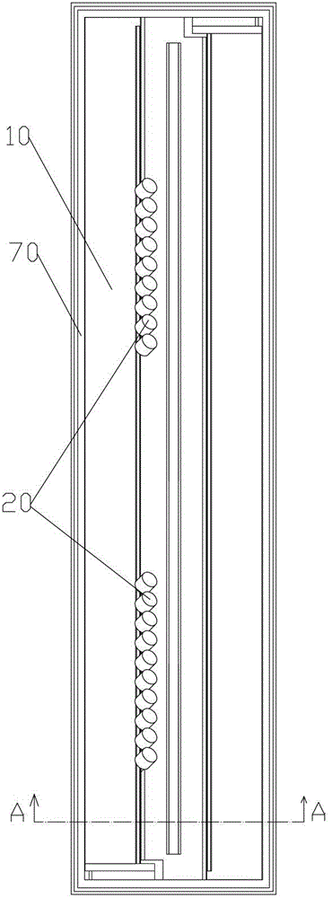
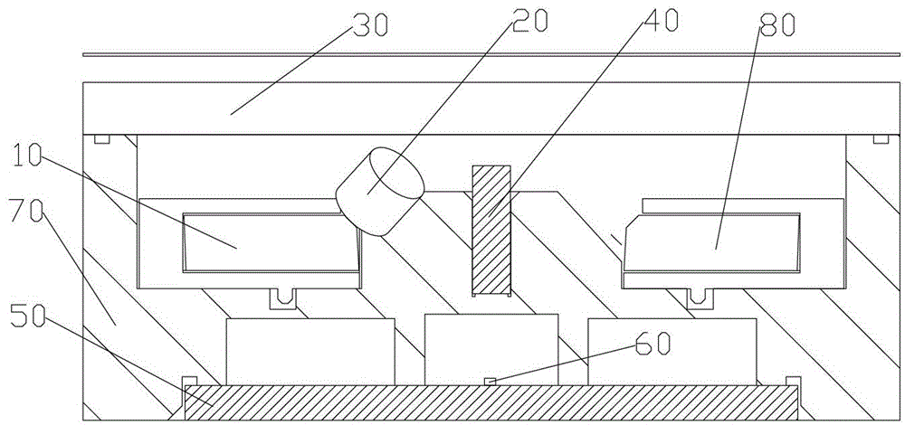
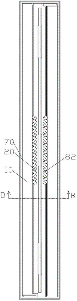
[0026] As a first aspect of the present invention, a light emitting device is provided. Such as Figure 1 to Figure 6 As shown, the light-emitting device includes: a first light source 10; a first light guide 20. The angle of the first light guide 20 is adjustable at the light exit of the first light source 10 to change the light exit angle of the first light guide 20. Since the angle between the first light guide 20 and the first light source 10 can be adjusted, by changing the angle between the first light guide 20 and the first light source 10, the exit angle of the light from the first light source 10 can be changed, thereby The incident angle of the light irradiated on the image is changed, so that the light-emitting device of the present ...


PUM


Abstract

The invention provides a light-emitting device and an image sensor. The light-emitting device comprises a first light source and a first light guiding part, wherein the first light guiding part is arranged at the position of a light outlet of the first light source in an adjustable angle mode to change a light outlet angle of the first light guiding part. Due to the fact that the angle between the first light guiding part and the first light source is adjustable, an outgoing angle of light of the first light source can be changed through changes of the included angle between the first light guiding part and the first light source so as to change an incoming angle of light which lights on an image, and the light-emitting device can be used for identifying a false proof mark which is made of optically variable ink and the hologram image. Meanwhile, the light-emitting device has the advantages of being simple in structure and low in manufacturing cost.

Description

Technical field [0001] The present invention relates to the technical field of sensors, and more specifically, to a light emitting device and an image sensor. Background technique [0002] With the continuous development of anti-counterfeiting technology, optical color-changing inks and holographic images have been widely used in the field of anti-counterfeiting. Optical color-changing inks and holographic images will show different colors or patterns with different incident angles of external light. Therefore, in order to recognize the anti-counterfeiting mark made of optically variable ink and holographic image, the incident angle of external light needs to be changed. [0003] The image sensor in the prior art (for example: contact image sensor), because the emitting angle of the light-emitting device (the angle between the horizontal direction is 45 degrees) is always the same, so it cannot be used to identify the optical color ink and the holographic image Anti-counterfeitin...

Claims


Application Information

Patent Timeline
Patent Type & Authority Applications(China)
IPC IPC(8): F21V17/02F21V8/00H04N1/028
Inventor 张文波王虎岩王家重
Owner WEIHAI HUALING OPTO ELECTRONICS CO LTD
Why Eureka
Try Eureka