Fluorescence excitation testing device

A testing device and fluorescence excitation technology, applied in the direction of fluorescence/phosphorescence, material excitation analysis, etc., can solve the problems of scratches or pits, emission light errors, uneven surface of phosphors, etc. Lighting efficiency, the effect of low total light source power

Inactive Publication Date: 2013-10-09
九江智汇科技新材料有限公司
View PDF7 Cites 3 Cited by
  • Summary
  • Abstract
  • Description
  • Claims
  • Application Information

AI Technical Summary

Problems solved by technology

[0006] The shortcoming of this test device is: before testing, need to add fluorescent powder in the powder pan 104, the fluorescent powder is compacted, and utilize auxiliary tool to scrape the upper surface of fluorescent powder, so that after the light source shines on the fluorescent powder upper surface , the excited fluorescence can be emitted uniformly; however, this method has many defects:
[0007] 1) Due to this method of sample loading, the phosphor powder must be compacted, otherwise the surface of the phosphor powder will be uneven; but because the force of manual compaction is different each time, the surface density of the phosphor powder will be different, so in different tests, in When the excitation light is irradiated on the surface of the phosphor, there will be errors in the emitted light generated by the excitation of the phosphor
[0008] 2) It is difficult to ensure the flatness of the phosphor surface, and scratches or pits often appear, which leads to deviations in the direction of emitted light after the phosph

Method used


Image

  • Fluorescence excitation testing device
  • Fluorescence excitation testing device
  • Fluorescence excitation testing device

Examples


Embodiment Construction

[0031] In order to make the object, technical solution and advantages of the present invention clearer, the present invention will be described in further detail below in conjunction with specific embodiments and with reference to the accompanying drawings.

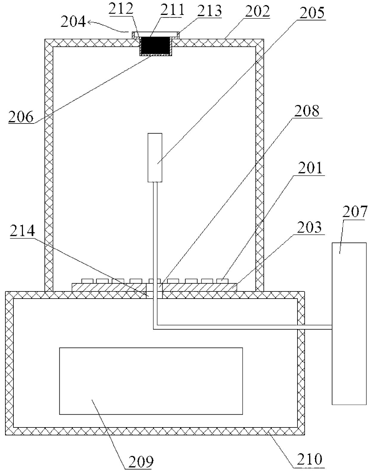
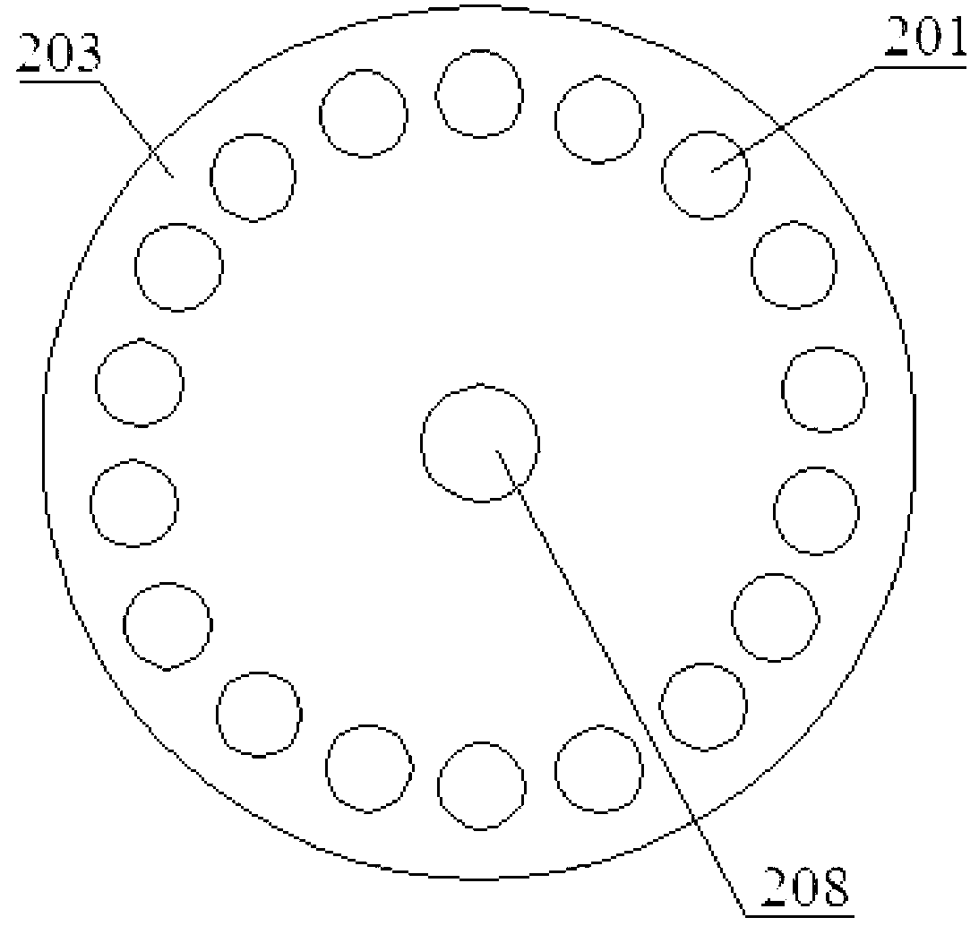
[0032] One embodiment of the present invention provides a fluorescence excitation test device, which includes a dark box for light shielding, a sample plate for placing a test sample on the top of the dark box, and a plurality of excitation devices at the bottom of the dark box. A light source, and a light receiver arranged between the sample disk and the excitation light source and located in the middle of the dark box; wherein, the bottom of the sample disk is transparent, and the plurality of excitation light sources are symmetrically distributed in the dark box Bottom; the plurality of excitation light sources emit excitation light, the test sample irradiated into it through the transparent bottom of the sample plate a...


PUM


Abstract

The invention discloses a fluorescence excitation testing device. The fluorescence excitation testing device comprises a camera obscura used for light shielding, a sample tray which is arranged at the top of the camera obscura and used for placing a tested sample, a plurality of excitation light sources arranged at the bottom of the camera obscura, as well as an optical receiver which is arranged between the sample tray and the excitation light source and positioned in the middle of the camera obscura, wherein the bottom of the sample tray is transparent, the plurality of excitation light sources are symmetrically distributed at the bottom of the camera obscura and emit excitation light which irradiates onto the tested sample in the sample tray through the transparent bottom of the sample tray and excites the tested sample to emit excited light, and the optical receiver is used for collecting mixed light of the excitation light and the excited light. According to the fluorescence excitation testing device disclosed by the invention, measurement results are accurate and have very high reference values.

Description

technical field [0001] The invention relates to the technical field of photoelectric detection, in particular to a fluorescence excitation test device. Background technique [0002] The fluorescence excitation test device is a test device for measuring the optical parameters of the test substance by exciting the test substance to emit light and testing the spectrum of the excited light (usually fluorescence). [0003] Refer to attached figure 1 , is a structural schematic diagram of a fluorescence excitation test device in the prior art. [0004] The fluorescent excitation testing device of the prior art comprises an excitation light source 101, a dark box 102 for exposure and measurement, an adjustable diaphragm 103 is arranged in the dark box 102 close to the bottom of the excitation light source 101, and a fluorescent powder test chamber is arranged below the excitation light source 101. A sample powder pan 104 is provided on the dark box 102 with an emitting light rece...

Claims


Application Information

Patent Timeline
IPC IPC(8): G01N21/64
Inventor 张国生徐艳芳王燕
Owner 九江智汇科技新材料有限公司
Why Eureka
Try Eureka