
Camera flash unit

A flash device and camera technology, applied in optics, instruments, photography, etc., can solve the problems of low sensitivity, affecting the shooting effect, high contrast and color distortion, and achieve the effect of uniform illumination and improved shooting effect.

Inactive Publication Date: 2013-10-09
SHAOGUAN CITY INST OF TECHNICIAN
View PDF4 Cites 0 Cited by
  • Summary
  • Abstract
  • Description
  • Claims
  • Application Information

AI Technical Summary

Problems solved by technology

[0002] At present, the shooting effect of the camera is getting closer and closer to the real scene, but for macro shooting, there are the following problems: (1) Clear and delicate picture quality and sufficient depth of field are required, so the sensitivity of shooting It will be set lower, such as 100 or 200, and the aperture will be set smaller, such as 14 or 16; (2) If you use a hand-held method to shoot, you also need a faster and safe shutter, such as setting the speed to 200; (3) If a close-up ring is added to increase the magnification, how many times the magnification is increased will be a fraction of the original exposure
If the low exposure value formed by low sensitivity, small aperture and fast shutter is divided by a magnification value, then the actual exposure value will become very small, and the requirements for the guide number of the flash will be very high. The existing macro flash has a small guide number and generally cannot meet the requirements of the above situations
The existing macro flash is fixed on the lens, and the flash can only illuminate the subject in one direction from the front, and cannot achieve side or back illumination
The existing macro flash generally does not have a soft light device, and the light shining on the subject is very hard, which will produce high contrast and color distortion, which will affect the shooting effect

Method used


Image

  • Camera flash unit

Examples


Embodiment Construction

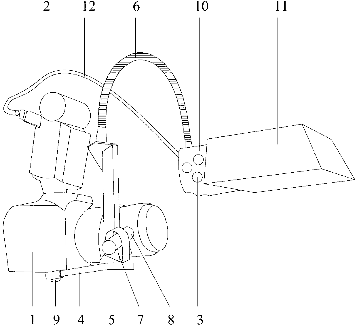
[0024] like figure 1 A camera flash device of the present invention shown includes a flash device body 2 and a luminous body 3 electrically connected to the flash device body 2. The flash device also includes a soft light device and a positioning device for controlling the displacement of the luminous body 3. The positioning The device includes a transverse guide rod 4 and a longitudinal connecting rod 5 installed on the transverse guide rod 4 , the upper end of the longitudinal connecting rod 5 is connected to the luminous body 3 through a universal adjustment tube 6 . The illuminant 3 can be connected with the flash device body 2 through the data line 12 . The universal adjustment tube 6 can timely adjust the illumination angle of the illuminant 3 to meet different photography requirements.

[0025] One end of the transverse guide rod 4 is movably connected with the camera 1 , and an auxiliary illuminant 8 is installed at the other end. A rotating sleeve 7 that rotates aro...


PUM


Abstract

The invention relates to a camera flash unit. The camera flash unit comprises a flash unit body and a light-emitting body electrically connected with the flash unit body. The flash unit body further comprises a soft light device and a locating device controlling the light-emitting body to move. The locating device comprises a transverse guide rod, and a longitudinal connection rod installed on the transverse guide rod. The upper end of the longitudinal connection rod is connected with the light-emitting body through a universal adjusting pipe. A light source of the camera flash unit can be placed at will so that the front, left, right and backlight irradiation effect can be achieved flexibly, the illumination on the surface of a subject to be shot is uniform and soft, and the camera flash unit is suitable for microspur shooting.

Description

technical field [0001] The invention relates to a photographic device, in particular to a flash device for a camera. Background technique [0002] At present, the shooting effect of the camera is getting closer and closer to the real scene, but for macro shooting, there are the following problems: (1) Clear and delicate picture quality and sufficient depth of field are required, so the sensitivity of shooting It will be set lower, such as 100 or 200, and the aperture will be set smaller, such as 14 or 16; (2) If you use a hand-held method to shoot, you also need a faster and safe shutter, such as setting the speed to 200; (3) If a close-up ring is added to increase the magnification, how many times the magnification is increased will be a fraction of the original exposure. If the low exposure value formed by low sensitivity, small aperture and fast shutter is divided by a magnification value, then the actual exposure value will become very small, and the requirements for th...

Claims


Application Information

Patent Timeline
IPC IPC(8): G03B15/05G03B15/06
Inventor 廖卓兴
Owner SHAOGUAN CITY INST OF TECHNICIAN
Learn More