Sound production device

A sound-generating device and loudspeaker technology, applied in the field of electro-acoustics, can solve problems such as poor hearing, affecting vibration of the diaphragm, and unbalanced air pressure in the rear acoustic cavity, and achieve the effect of improving acoustic performance

Inactive Publication Date: 2013-10-09
GOERTEK INC
View PDF5 Cites 53 Cited by
  • Summary
  • Abstract
  • Description
  • Claims
  • Application Information

AI Technical Summary

Problems solved by technology

Under certain circumstances, the rear acoustic cavity of the sound-generating device is a sealed structure. For this structure, the air pres

Method used


Image

  • Sound production device
  • Sound production device
  • Sound production device

Examples


Embodiment Construction

[0023] The present invention will be further described in detail below in conjunction with the accompanying drawings and specific embodiments.

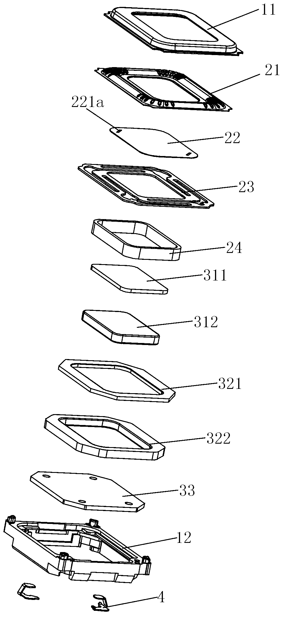
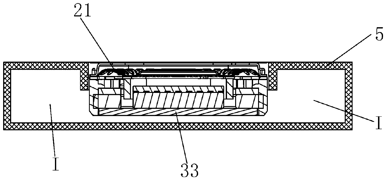
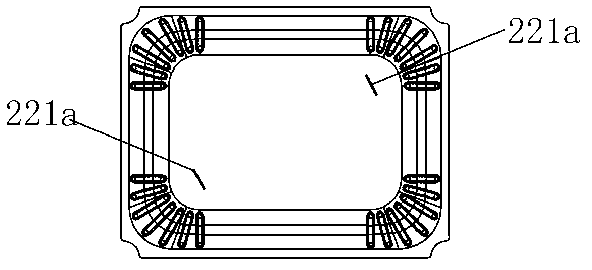
[0024] Such as figure 1 and figure 2 As shown, the sound generating device includes a speaker unit and a peripheral casing 5 for accommodating and fixing the speaker unit. Wherein, the loudspeaker unit mainly includes a vibration system, a magnetic circuit system, and a protective frame for accommodating and fixing the vibration system and the magnetic circuit system, and also includes an electrical connector 4 for electrically connecting the internal circuit and the external circuit of the sound generating device. The vibration system includes a diaphragm, a voice coil 24 combined with the lower side of the diaphragm, and a strut 23; the strut 23 is fixedly combined with the voice coil 24 to prevent polarization during the vibration of the voice coil 24; the vibration of this embodiment The diaphragm is composed of two parts, incl...


PUM


Abstract

The invention discloses a sound production device which comprises a loudspeaker monomer and a peripheral shell used for containing and fixing the loudspeaker monomer. The loudspeaker monomer comprises a vibrating diaphragm. Spaces on the rear side of the vibrating diaphragm form rear vocal cavities and the rear vocal cavities are composed of the loudspeaker monomer and the peripheral shell together. Moreover, the rear vocal cavities are of sealed structures. A leakage hole is formed in the vibrating diaphragm and communicated with the two sides of the vibrating diaphragm. A leakage hole is of a hole-shaped structure or a slit-shaped structure. Due to the structure, air flows in the rear vocal cavities are balanced, and tone quality is adjusted, so that acoustic performance of the sound production device with the completely sealed rear vocal cavities is improved.

Description

technical field [0001] The invention relates to the field of electroacoustics, in particular to a sounding device. Background technique [0002] The sound-generating device includes a loudspeaker unit and a peripheral casing. The loudspeaker unit includes a vibration system, a magnetic circuit system, and a protective frame for accommodating and fixing the vibration system and the magnetic circuit system. The vibration system usually includes a diaphragm and a voice coil combined on the lower side of the diaphragm, and the magnetic circuit system forms a magnetic gap for accommodating the voice coil. The space on the front side of the diaphragm of the sound-generating device forms the front acoustic cavity, and the space on the rear side of the diaphragm forms the rear acoustic cavity, and the front acoustic cavity and the rear acoustic cavity are mutually isolated structures. The rear acoustic cavity is the enclosed space between the loudspeaker unit and the peripheral she...

Claims


Application Information

Patent Timeline
IPC IPC(8): H04R9/06
Inventor 王继宗王泽葛连山
Owner GOERTEK INC
Why Eureka
Try Eureka