Motor vehicle door lock

A motor vehicle door lock and lock technology, which is applied in vehicle locks, automatic fastening/unlocking, building locks, etc., can solve problems such as functional interference and delay in movement of locking levers, and achieve the effect of high functional reliability.

Active Publication Date: 2013-10-09
KIEKERT & KOMMANDITGES
View PDF2 Cites 10 Cited by
  • Summary
  • Abstract
  • Description
  • Claims
  • Application Information

AI Technical Summary

Problems solved by technology

This can cause functional disturbances in practice, for example, if the movement of the locking lever is blocked or delayed due to corrosion, aging, etc.
Furthermore, suc

Method used


Image

  • Motor vehicle door lock

Examples


Embodiment Construction

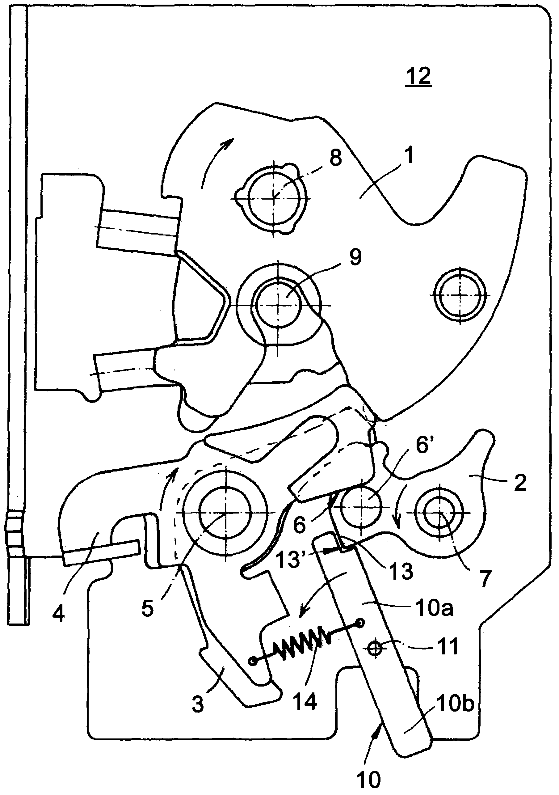
[0024] The drawing shows a motor vehicle door lock which is equipped with a locking device 1 , 2 , 3 comprising a rotary latch 1 , a locking pawl 2 and a pawl 3 . Furthermore, the release lever 4 acting on the locking devices 1 , 2 , 3 can be seen.

[0025] In order to open the locking device 1 , 2 , 3 , the release lever 4 must be pivoted clockwise about its axis 5 , as indicated by the arrow shown in the drawing. As a result, the release lever 4 acts with the edge 6 on the pin 6 ′ of the locking pawl 2 . As a result, the locking pawl 2 rotates counterclockwise about its axis 7 in the direction of the arrow shown. As soon as the locking pawl 2 has moved away from the locking pawl 3 , the rotary latch 1 can be pivoted clockwise about its axis 8 with the aid of a spring and release a locking pin 9 which is only schematically shown. The locking pin 9 is connected to a not shown motor vehicle door.

[0026] A further essential structure includes a locking lever 10 , which is m...


PUM


Abstract

The invention relates to a motor vehicle door lock equipped with a locking mechanism (1, 2, 3), an actuation lever unit that acts on the locking mechanism (1, 2, 3) and includes a release lever (4), and a catch lever (10). The catch lever (10) blocks the locking mechanism (1, 2, 3) at least when acceleration forces of a given magnitude occur, e.g. in case of an accident (crash). According to the invention, the catch lever (10) blocks the locking mechanism (1, 2, 3) in the event of a crash while releasing the locking mechanism (1, 2, 3) only for normal opening operation.

Description

technical field [0001] The invention relates to a motor vehicle door lock with a locking device, an actuating lever mechanism with a release lever acting on the locking device and a locking lever at least - for example in the event of an accident (collision accident) )—lock the locking device in the event of a pre-determined acceleration force. Background technique [0002] Actuation rod mechanisms typically include one or more rods. Usually a minimum of internal actuation levers, external actuation levers and release levers are used. Furthermore, the actuating lever mechanism usually also includes a coupling lever. In this way the locking device can be opened if the actuating lever mechanism is loaded. For this purpose, the release lever generally acts on a pawl of the locking device and disengages the pawl from the associated rotary latch. The rotary latch then opens with the aid of a spring and releases the previously caught locking pin. The associated motor vehicle ...

Claims


Application Information

Patent Timeline
IPC IPC(8): E05B65/32E05B77/54E05B85/22
CPCE05B77/06E05B85/26Y10S292/22Y10T292/0949E05B77/12
Inventor T·贝代尔C·特普费尔
Owner KIEKERT & KOMMANDITGES
Why Eureka
Try Eureka