Tablet feeder

An applicator and tablet technology, which is applied in the field of tablet applicators, can solve the problems of contaminating fingers, sending tablets to diseased places, and affecting treatment effects.

Inactive Publication Date: 2013-10-16
李永刚
View PDF0 Cites 4 Cited by
  • Summary
  • Abstract
  • Description
  • Claims
  • Application Information

AI Technical Summary

Problems solved by technology

At present, tablets are generally administered to the affected area with fingers. This method of administration pollutes the fingers, which is

Method used


Image

  • Tablet feeder

Examples


Embodiment Construction

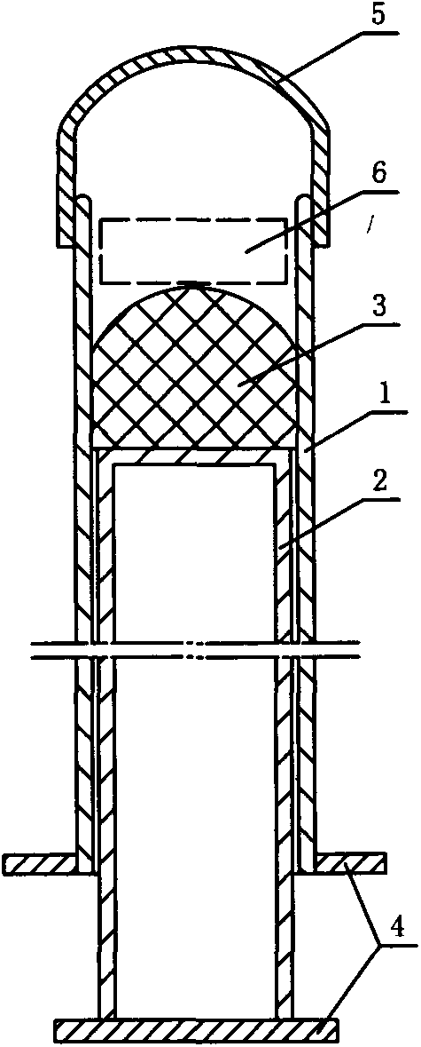
[0013] Such as figure 1 As shown, the tablet dispenser includes a sleeve 1 with openings at both ends, and the upper end of the sleeve 1 is rounded, and a push rod 2 is arranged inside the sleeve 1, and a push rod made of silica gel is provided at the upper end of the push rod 2. Block 3, the upper end of the push block 3 is a convex arc surface, so that the tablet can be pushed out of the casing 1 better.

[0014] Both the casing 1 and the push rod 2 are made of PP material, and the push rod 2 is tubular, that is, hollow, which can save materials and reduce production costs. The upper end of the casing 1 is provided with an antibacterial cap 5 which can seal the opening.

[0015] Both the ends of the casing 1 and the push rod 2 are provided with lugs 4. By setting the lugs 4 on the push rod 2, the length of the push rod 2 protruding from the upper end of the sleeve 1 can be prevented from being too long. The ear socket 4 is convenient for the user to exert force on the push...


PUM


Abstract

The invention discloses a tablet feeder. The tablet feeder comprises a sleeve pipe, wherein openings are formed in the two ends of the sleeve pipe, a push rod is arranged in the sleeve pipe, a push block is arranged at the upper end of the push rod, and the end portion of the push block is a cambered surface protruding outwards. A tablet is put on the push block from the opening in the upper end of the sleeve pipe, the sleeve pipe is inserted into a sick portion of the vagina of a patient, the push rod is pushed, the tablet is conveyed to the sick portion from the sleeve pipe at the moment the push rod is pushed and a lug seat of the push rod is clamped on the sleeve pipe, the sleeve pipe is pulled outwards, and vagina tablet feeding is finished. The tablet feeder is convenient to use, clean and sanitary and reduces the probability of cross infection.

Description

technical field [0001] The invention relates to a tablet dispenser. Background technique [0002] The treatment of many gynecological diseases is achieved through intravaginal administration, which can directly kill or inhibit the pathogenic microorganisms parasitic in the vagina. At present, tablets are generally administered to the affected area with fingers. This method of administration pollutes the fingers, which is very unhygienic, and when the affected area is deep, the fingers cannot deliver the tablet to the affected area, which affects treatment effect. Contents of the invention [0003] The technical problem to be solved by the present invention is to provide an easy-to-use tablet dispenser. [0004] In order to solve the above-mentioned technical problems, the present invention includes a casing with two ends open, a push rod is arranged inside the casing, and a push block is arranged at the upper end of the push rod, and the end of the push block is a convex...

Claims


Application Information

Patent Timeline
IPC IPC(8): A61M31/00
Inventor 李永刚
Owner 李永刚
Why Eureka
Try Eureka