Metal rod automatic feeding device for heating furnace

An automatic feeding and metal bar technology, which is applied in the directions of transportation and packaging, conveyor objects, etc., can solve the problem that the feeding cannot be controlled by equipment synchronously, and achieve the effect of saving manpower, improving the degree of automation, and ensuring synchronous operation.

Active Publication Date: 2013-10-16
JIANGSU HONGBAO HARDWARE
View PDF8 Cites 53 Cited by
  • Summary
  • Abstract
  • Description
  • Claims
  • Application Information

AI Technical Summary

Problems solved by technology

However, the process of putting the metal round rods into the feeding trough is mainly realized manually. The main reason is that there is interference of electric

Method used


Image

  • Metal rod automatic feeding device for heating furnace
  • Metal rod automatic feeding device for heating furnace

Examples


Embodiment 1

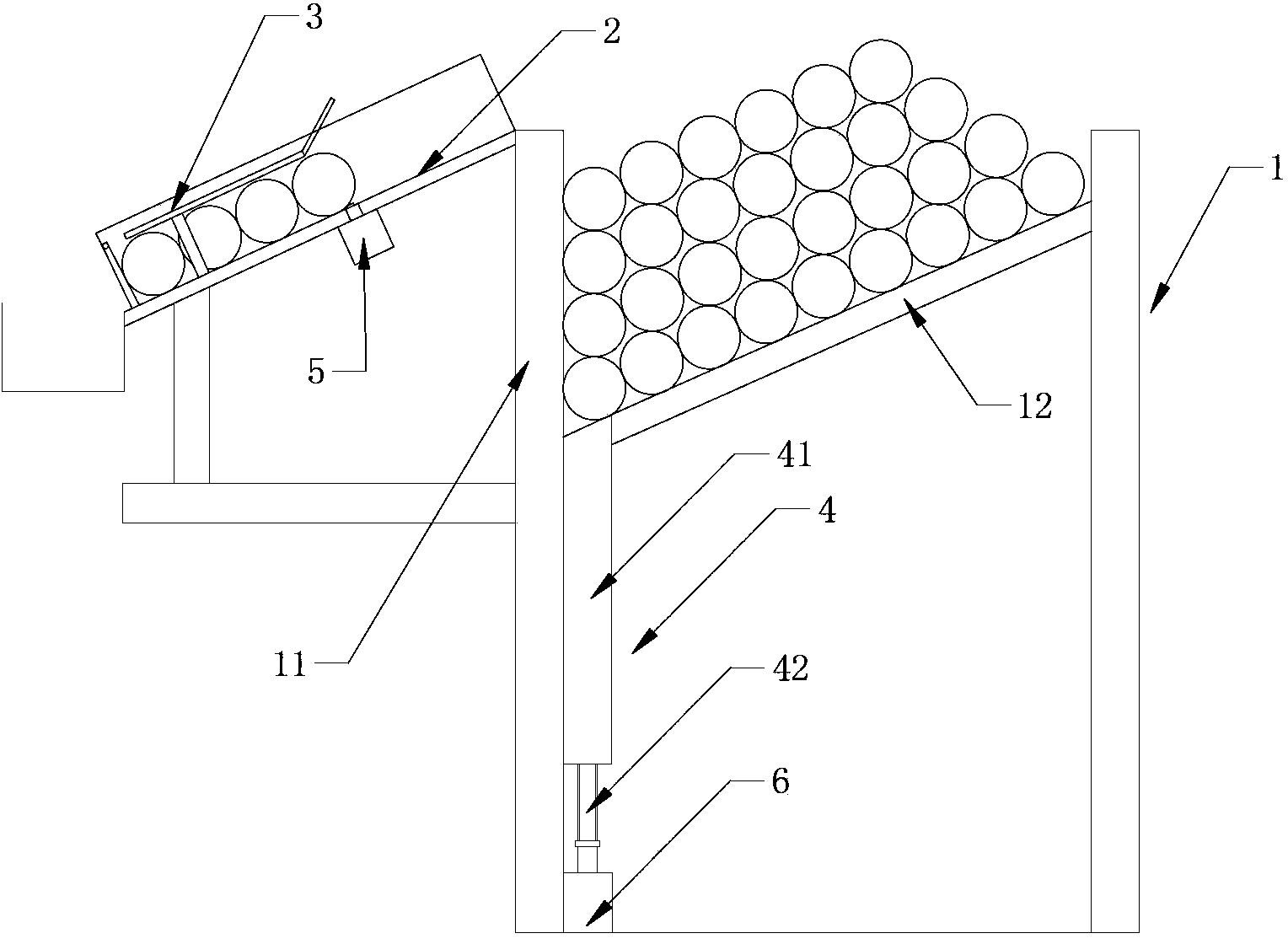
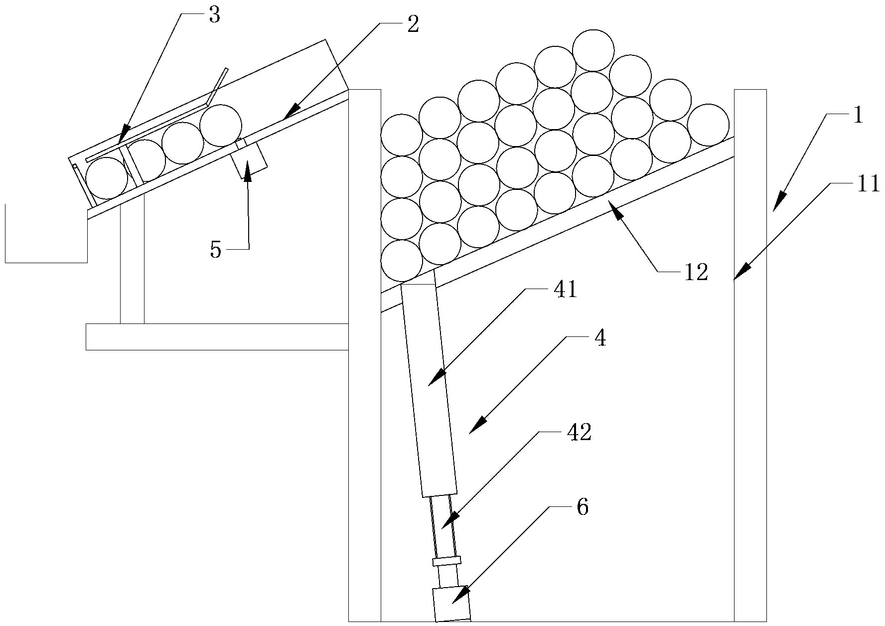
[0019] Such as figure 1 As shown, a metal rod automatic feeding device for a heating furnace includes a material storage box 1 and a material guide trough 2, the material storage box 1 includes a material storage chamber, the material storage chamber includes a bottom plate 12 and side plates, the The bottom plate 12 of the storage chamber is inclined; the material guide chute 2 is installed on the outer wall of the storage chamber and is located on the low side of the inclined bottom plate 12, and the material guide trough 2 is also inclined and the direction of inclination is the same as that of the bottom plate 12 ; The material guide trough 2 is provided with a material retaining device that can block or release the metal rod, and the material retainer device includes a material retaining plate that is movable up and down on the bottom of the material guide trough 2, and the material retaining plate and the cylinder piston rod connection. The cylinder can be used to pull ...

Embodiment 2

[0024] The structure of this embodiment is the same as that of Embodiment 1, except that the jacking mechanism 4 is different. The jacking mechanism 4 includes a lead screw 42 and a jacking plate 41 threadedly connected with the lead screw 42. The upper end of the jacking plate 41 faces The lower side of the bottom plate 12 is inclined, and the upper end of the lifting plate 41 is set as a horizontal plane or an inclined surface in the same direction as the bottom plate 12. The lead screw 42 is connected with the jacking power device. Like this, the up-and-down movement direction of the jacking plate 41 forms a certain angle with the vertical plane, so the upper end of the jacking plate 41 can be set to an inclined surface or directly set to a horizontal plane, then, when the jacking plate 41 moves upwards, it can still Effectively push the metal rods, and by optimizing the inclination angle of the lifting plate 41, only two metal rods can be lifted at most.


PUM


Abstract

The invention discloses a metal rod automatic feeding device for a heating furnace. The metal rod automatic feeding device for the heating furnace comprises a material storage box and a material guide groove, wherein the material storage box comprises a material storage chamber, a bottom plate of the material storage chamber is arranged obliquely, the material guide groove is formed in the outer wall of the material storage chamber and is located at a lower side of the oblique bottom late, the material guide groove is also arranged obliquely, and the oblique direction of the material guide groove is the same as the oblique direction of the bottom plate. A material blocking device used for blocking or releasing a metal rod is arranged on the material guide groove and is in linkage with a material pushing device of the heating furnace, a first sensor used for detecting the position of the metal rod is arranged on the material guide groove, a passing groove is formed in the bottom plate, a jacking mechanism is installed under the material storage chamber, a power end of the jacking mechanism penetrates through the passing groove and can push a metal plate into the material guide groove, the jacking mechanism is connected with a jacking power device, and the first sensor and the jacking power device are both connected with a controller. The automatic feeding device can replace workers for material feeding, improves feeding efficiency, is operated along with existing equipment synchronously, saves manpower and reduces cost.

Description

technical field [0001] The invention relates to an automatic feeding device for heating furnaces in the forging industry, in particular to an automatic feeding device for metal rods used in the heating furnace. Background technique [0002] In the current common heating furnace, it is necessary to place the metal round bar in the feeding trough of the heating furnace, and then use the cylinder to push the metal round bar axially into the heating furnace. However, the process of putting the metal round rods into the feeding trough is mainly realized manually. The main reason is that there is interference of electric field and magnetic field in the heating furnace, and the general mechanical feeding cannot be compared with the existing ones. device synchronization control. Contents of the invention [0003] The technical problem to be solved by the present invention is to provide an automatic feeding device for metal rods used in heating furnaces, which can replace manual f...

Claims


Application Information

Patent Timeline
IPC IPC(8): B65G47/14
Inventor 秦卫华朱剑峰
Owner JIANGSU HONGBAO HARDWARE
Why Eureka
Try Eureka