Discharging device suitable for construction of internal structure of subway station
A technology for internal structures and subway stations, applied in infrastructure engineering, construction, etc., can solve the problems of separation of aggregates in conveying efficiency, high construction costs, and high noise, and achieve the effect of reducing operating intensity and low cost
- Summary
- Abstract
- Description
- Claims
- Application Information
AI Technical Summary
Problems solved by technology
Method used
Image
Examples
Embodiment 1
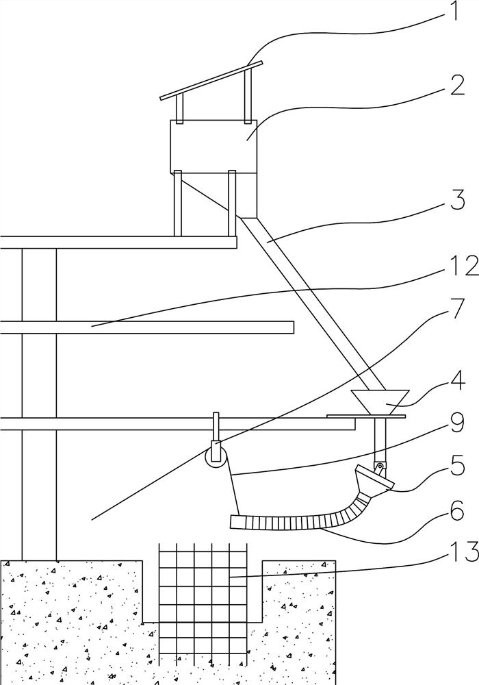
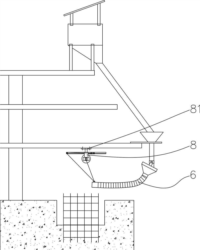
[0028] Such as figure 1 , 2 In, 8, a kind of unloading device that is applicable to the inner structure construction of subway station, comprises hopper and feeding pipe conveying structure, in the position close to pouring warehouse 13, the bottom of third hopper 5 and feeding pipe conveying structure is hinged, the first The three hoppers 5 are connected with one end of the feeding hose 6, and the other end of the feeding hose 6 is connected with the traction device, and a steel wire rope is arranged in the traction device, and the steel wire rope is connected with the feeding hose 6 for pulling the free end of the feeding hose 6 Swing in the scope of pouring bin 13, to discharge material evenly. Preferably, the feeding hose 6 is a corrugated tube or a rubber tube. If a rubber tube is used, support rings are provided at intervals in the rubber tube to prevent the rubber tube from being completely closed and affecting the cutting efficiency.
[0029] The preferred solution...
Embodiment 2
[0032] On the basis of Example 1, the preferred scheme is as figure 1 Among them, the traction device is a pulley 7, and the pulley 7 is preferably fixed on the top of the pouring bin 13, or it can be on the top side, and the wire rope goes around the pulley 7 to connect with the feeding hose 6. This solution is suitable for smaller pouring bins 13, and has a simple structure, and operators can operate outside the bins.
Embodiment 3
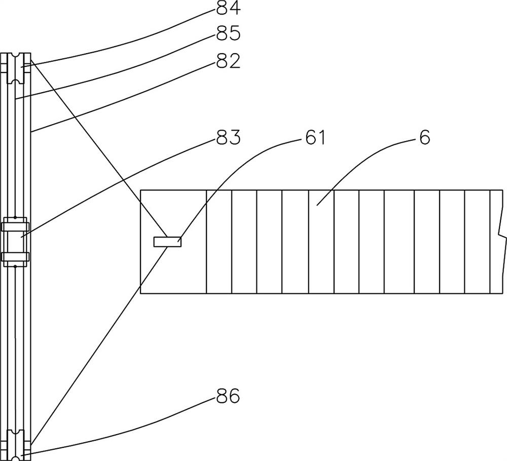
[0034] On the basis of Example 1, the preferred scheme is as figure 2 Among them, the traction device is a pulling device 8, the pulling device 8 includes at least one track, the track is fixedly installed on the top or side of the pouring warehouse 13, guide wheels are provided at both ends of the track, and there are Dolly, at least one end of the dolly is connected with the steel wire rope, and the steel wire rope is connected with the free end of the feeding hose 6 around the guide wheel. When the trolley is driven to walk along the track, it drives the steel wire rope to pull up or put down the free end of the feeding hose 6, so as to realize uniform distribution.
PUM
 Abstract
Description
Claims
Application Information
 - R&D
- Intellectual Property
- Life Sciences
- Materials
- Tech Scout
- Unparalleled Data Quality
- Higher Quality Content
- 60% Fewer Hallucinations
Browse by: Latest US Patents, China's latest patents, Technical Efficacy Thesaurus, Application Domain, Technology Topic, Popular Technical Reports.
© 2025 PatSnap. All rights reserved.Legal|Privacy policy|Modern Slavery Act Transparency Statement|Sitemap|About US| Contact US: help@patsnap.com


