Clock data recovery circuit and receiver including the same

a clock data recovery and receiver technology, applied in pulse manipulation, pulse technique, synchronisation signal speed/phase control, etc., can solve the problems of clock data recovery circuit malfunction, clock data recovery circuit performance degradation, etc., and achieve the effect of enhancing the performance of the receiver including the clock data recovery circui

Active Publication Date: 2018-11-20
SAMSUNG ELECTRONICS CO LTD
View PDF16 Cites 0 Cited by
  • Summary
  • Abstract
  • Description
  • Claims
  • Application Information

AI Technical Summary

Benefits of technology

[0004]Methods and apparatuses consistent with exemplary embodiments provide a clock data recovery circuit having enhanced input jitter tolerance.
[0005]Methods and apparatuses consistent with exemplary embodiments provide a receiver including a clock data recovery circuit having enhanced input jitter tolerance.
[0008]The clock data recovery circuit according to exemplary embodiments may implement a uniform frequency transfer characteristic regardless of the operational conditions by controlling the gain of the proportional path so that the frequency step of the recovered clock signal may be uniform regardless of the operational conditions, and thus performance of the clock data recovery circuit and the receiver including the clock data recovery circuit may be enhanced.

Problems solved by technology

In recent electronic systems using complementary metal-oxide semiconductor (CMOS) integrated circuit (IC) technology, communication between chips may require fast speed and wide bandwidth.
If input jitter tolerance is not secured, the clock data recovery circuit may malfunction or performance of the clock data recovery circuit may be degraded.

Method used


Image

  • Clock data recovery circuit and receiver including the same
  • Clock data recovery circuit and receiver including the same
  • Clock data recovery circuit and receiver including the same

Examples


Embodiment Construction

[0033]Various example embodiments will be described more fully hereinafter with reference to the accompanying drawings, in which some example embodiments are shown. In the drawings, like numerals refer to like elements throughout. To avoid unnecessarily obscuring the details of the exemplary embodiments, redundant descriptions may be omitted.

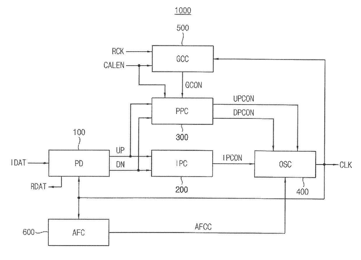
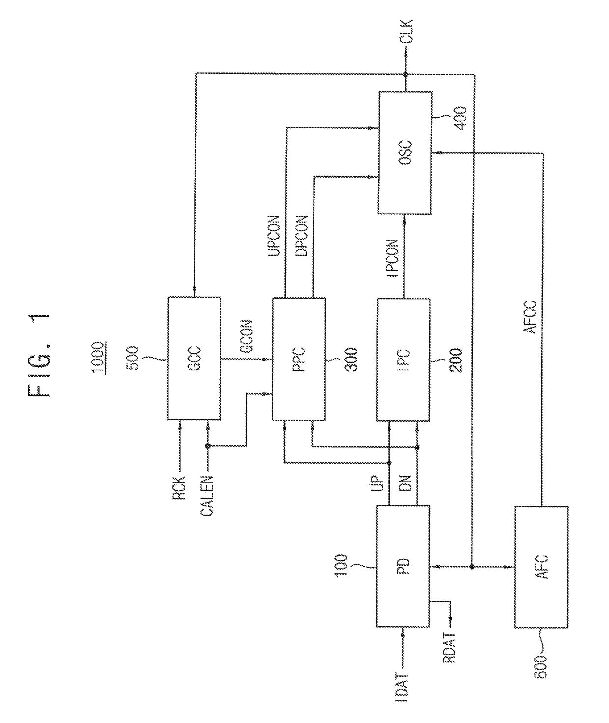
[0034]FIG. 1 is a block diagram illustrating a clock data recovery circuit according to an exemplary embodiment.

[0035]Referring to FIG. 1, a clock data recovery circuit 1000 may include a phase detector PD 100, an integral path circuit IPC 200, a proportional path circuit PPC 300, an oscillation circuit OSC 400 and a gain control circuit GCC 500. The clock data recovery circuit 1000 may further include an automatic frequency control circuit AFC 600.

[0036]The phase detector 100 may receive an input data signal IDAT through a communication channel from an external transmitter and receive a recovered clock signal CLK that is generated in the clock ...


PUM


Abstract

A clock data recovery circuit configured to generate frequency step that is uniform regardless of operational conditions of the clock data recovery circuit.

Description

CROSS-REFERENCE TO RELATED APPLICATION[0001]The present application claims priority under 35 USC § 119 from Korean Patent Application No. 10-2016-0181259, filed on Dec. 28, 2016, in the Korean Intellectual Property Office (KIPO), the disclosure of which is incorporated herein by reference in its entirety.BACKGROUND1. Field[0002]Methods and apparatuses consistent with exemplary embodiments of the present application relate to semiconductor integrated circuits, and more particularly to a clock data recovery circuit and a receiver including a clock data recovery circuit.2. Description of the Related Art[0003]In recent electronic systems using complementary metal-oxide semiconductor (CMOS) integrated circuit (IC) technology, communication between chips may require fast speed and wide bandwidth. Accordingly, each of the communication chips may include a high-speed input / output (I / O) interface circuit such as a serial link. In serial link communication, data may be provided through a comm...

Claims


Application Information

Patent Timeline
Patent Type & Authority Patents(United States)
IPC IPC(8): H04L7/033H03L7/085H03L7/099H04L7/04H03L7/08
CPCH04L7/0331H03L7/085H04L7/042H03L7/0995H03L7/0807H03L7/093H03L2207/06H04L7/0079H04L7/033H03K2005/00071H03L7/089H03L7/0997H03L7/1077
Inventor YOO, BYOUNG-JOOSONG, KYUNG-SEOKSONG, HO-BIN
Owner SAMSUNG ELECTRONICS CO LTD
Why Eureka
Try Eureka