Print head driving method and image formation apparatus using the same

a driving method and printing head technology, applied in the direction of instruments, visual presentations, computing, etc., can solve the problems of increasing the time required for the transmission of image data, increasing the printing time, and reducing resolution

Inactive Publication Date: 2007-02-15
FUTABA CORPORATION
View PDF0 Cites 1 Cited by
  • Summary
  • Abstract
  • Description
  • Claims
  • Application Information

AI Technical Summary

Benefits of technology

[0026] It is, therefore, an object of the present invention to provide a print head driving method used for a print head for controlling a gradation by combining a pulse accumulation method and a pulse weight-application method, allowing same time periods to be allotted for the transmission of image data to respective array light sources having different resolutions by using a control circuit without degrading a quality of image; and an image formation apparatus using such print head driving method.
[0039] In accordance with the present invention, a gradation of a print head employing an array light source of a lower resolution and an array light source of a higher resolution is controlled by simply combining a pulse weight-application method and a pulse accumulation method, and a combination ratio of the pulse weight-application method applied to the array light source having the higher resolution is set to be greater than that of the pulse weight-application method applied to the array light source having the lower resolution. Thus, it is possible to form an image at a proper speed without deteriorating a quality of the image.
[0041] In accordance with the present invention, a gradation of a print head employing an array light source of a lower resolution and an array light source of a higher resolution is controlled by simply combining a pulse weight-application method and a pulse accumulation method, and the odd-numbered light emitting elements and the even-numbered light elements are driven alternately once for each bit during the gradation control. Thus, it is possible to set a combination ratio of the pulse weight-application method applied to the array light source having the higher resolution to be equal to that of the pulse weight-application method applied to the array light source having the lower resolution. Further, steps of the gradation of photo-sensitized dots can be made uniform.
[0042] In accordance with the present invention, a gradation of a print head employing an array light source of a lower resolution and an array light source of a higher resolution is controlled by simply combining a pulse weight-application method and a pulse accumulation method, the odd-numbered light emitting elements and the even-numbered light elements are driven alternately once for each bit during the gradation control, and the order of activating the odd-numbered light emitting elements and the even-numbered light elements is changed for every single cycle of gradation control. Thus, it is possible to set a combination ratio of the pulse weight-application method for the array light sources having the higher resolution to be same as that for the array light sources having the lower resolution. Further, steps of the gradation of photo-sensitized dots can be made uniform.
[0044] In accordance with the present invention, a gradation of a print head employing an array light source of a lower resolution and an array light source of a higher resolution is controlled by a pulse accumulation pulse weight-application method. Further, in the array light source of the higher resolution, the odd-numbered light emitting elements and the even-numbered light elements are driven alternately once for each cycle of the gradation control or once for each bit during the gradation control, or the odd-numbered light emitting elements and the even-numbered light elements are driven once for each bit during the gradation control and the order of activating the odd-numbered light emitting elements and the even-numbered light elements is changed for every single cycle of gradation control. Thus, steps of the gradation of photo-sensitized dots can be made uniform.

Problems solved by technology

However, since a large number of image data must be transmitted from the control circuit to the driving circuit, the time required for the transmission of the image data is increased, which in turn increases the printing time.
However, the resolution is also reduced, and the quality of printed image is degraded.
In practice, however, there is an upper limit of the performance such as the driving frequency of a driver IC.
Therefore, there are occasions where the driving frequency cannot be doubled up.
Furthermore, if a high-frequency driver IC is used, the cost increases, and the entire circuit including a data transmission circuit is required to be processed faster.
Therefore, the entire production cost of the print head increases, thereby making the amplification of the driving frequency of the driving circuit impractical.

Method used


Image

  • Print head driving method and image formation apparatus using the same
  • Print head driving method and image formation apparatus using the same
  • Print head driving method and image formation apparatus using the same

Examples


first preferred embodiment

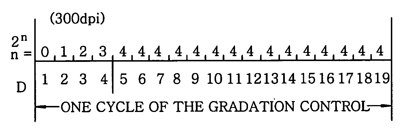
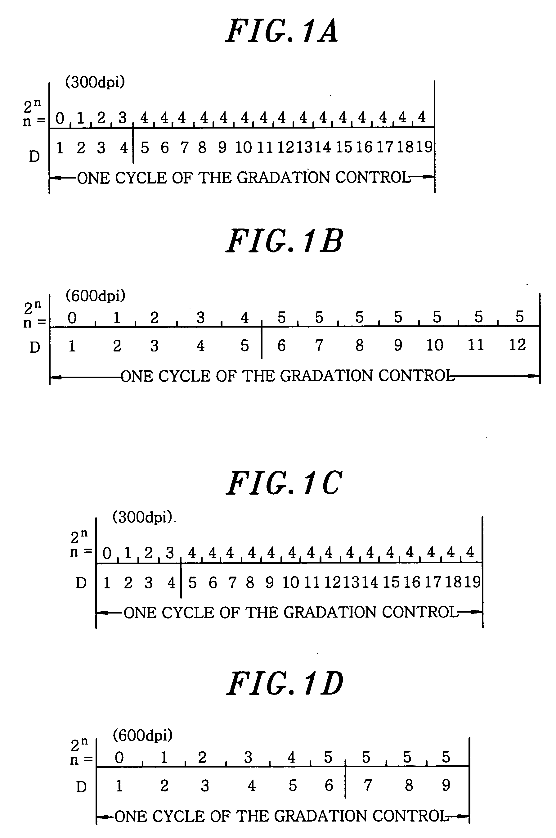
[0058]FIGS. 1A to 1D describe a gradation control method in accordance with a first preferred embodiment of the present invention.

[0059] The gradation control of array light sources shown therein is based on 8-bit image data. FIGS. 1A and 1C describe a case of using an array light source having a resolution of 300 dpi, whereas FIGS. 1B and 1D depict a case of using an array light source having a resolution of 600 dpi. Further, driving frequencies of driving circuits of the array light sources are same in both cases, and the time periods designated as “one cycle of the gradation control” in FIGS. 1A to 1D only show data transmission times, and the non-emission times are omitted therefrom for simplicity.

[0060] The array light source having the resolution of 300 dpi is used for generating, e.g., green or blue light, and fluorescent luminous tubes are employed therein. The array light source having the resolution of 600 dpi is used for generating red light, and LEDs are employed there...

second preferred embodiment

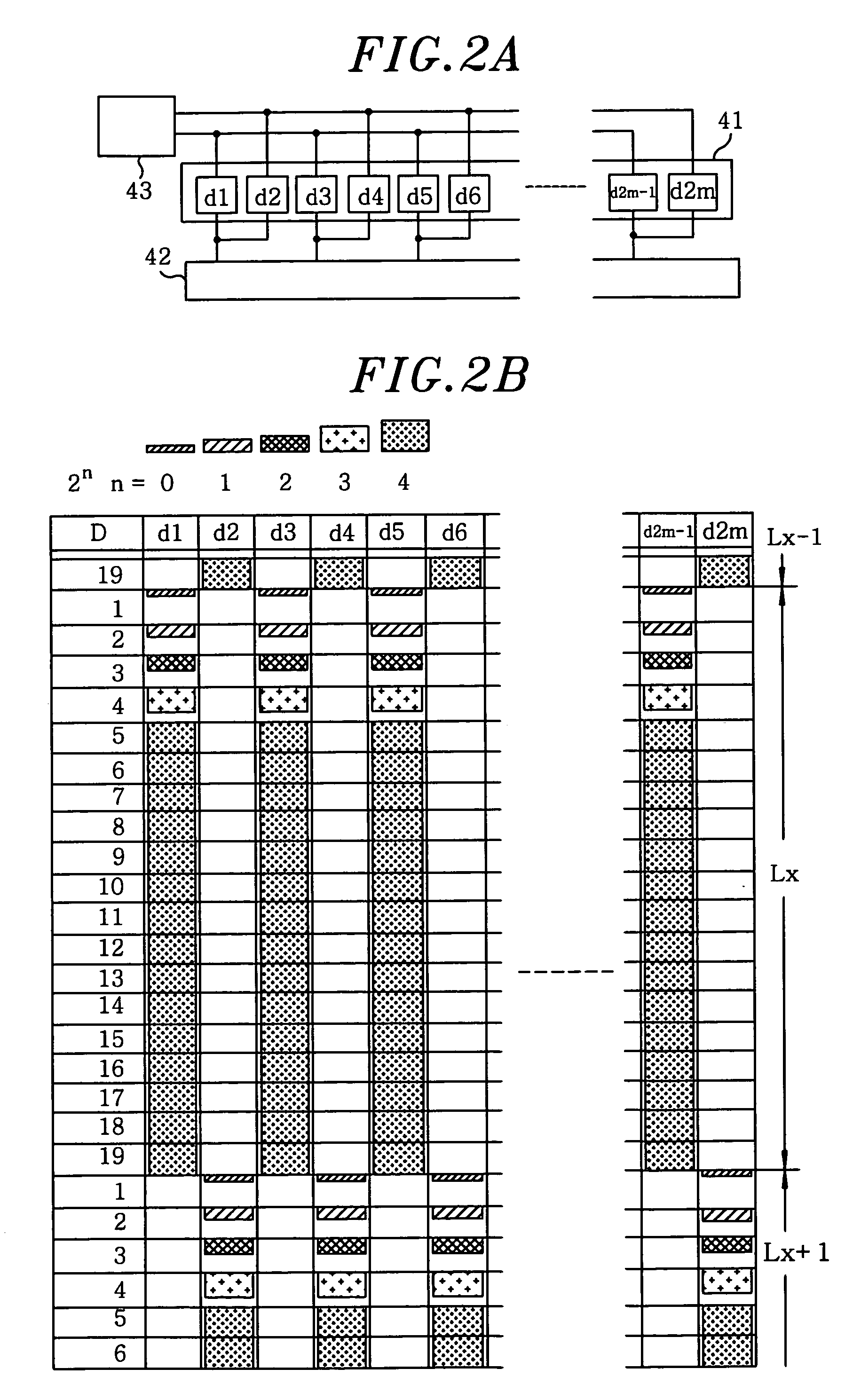
[0069]FIGS. 2A and 2B describe a gradation control method in accordance with a second preferred embodiment of the present invention, in which the pulse accumulation method and the pulse weight-application method are combined, and an interlace method for alternately driving odd-numbered light emitting elements and even-numbered light emitting elements alternately once for each cycle of gradation control is applied thereto.

[0070] Moreover, though a print head in this embodiment employs both an array light source having a resolution of 300 dpi and an array light source having a resolution of 600 dpi, the interlace method is only applied to the array light source having the resolution of 600 dpi. FIGS. 2A and 2B only illustrate the case of using the 600 dpi array light source.

[0071]FIG. 2A shows a driving circuit of an array light source 41 in which light emitting elements d1 to d2m formed of LEDs are installed in a pattern of an array. The array light source 41 has a resolution of 60...

third preferred embodiment

[0078]FIGS. 3A to 3E illustrate a gradation control method in accordance with a third preferred embodiment of the present invention. The method combines a driving method for alternating odd-numbered light emitting elements and even-numbered light emitting elements for each bit as well as combining a pulse accumulation method and a pulse weight-application method.

[0079] Further, although a print head in this embodiment employs both array light sources having a resolution of 300 dpi and an array light source having a resolution of 600 dpi, the method for alternating the light emitting elements once for each bit is applied only to the array light source of 600 dpi. Further, FIGS. 3A to 3E illustrate the gradation control of the array light source of 600 dpi, and only four light emitting elements d1 to d4 among light emitting elements d1 to d2m are shown therein.

[0080] Hereinafter, FIG. 3A will be explained first.

[0081] During a cycle of the gradation control Lx, image data is transm...


PUM


Abstract

A print head driving method controls a gradation of a print head employing an array light source of a lower resolution and an array light source of a higher resolution based on image data represented by 2n bits, wherein n is zero or a positive integer, and both of the array light sources are gradation-controlled by combining a pulse weight-application method and a pulse accumulation method. Further, a image formation apparatus controls a gradation of a print head employing an array light source of a lower resolution and an array light source of a higher resolution based on image data represented by 2n bits, wherein n is 0 or a positive integer, and both of the array light sources are controlled by a gradation control method employing a simple combination of a pulse weight-application method and a pulse accumulation method.

Description

FIELD OF THE INVENTION [0001] The present invention relates to a print head driving method for recording or forming an image on a photo-sensitive recording medium such as a printing paper by driving an array of light emitting elements according to image data, and also relates to an image formation apparatus using the print head driving method. BACKGROUND OF THE INVENTION [0002] Conventionally, fluorescent luminous tubes, light emitting diodes (LEDs), organic electroluminescent (EL) devices, and so forth are employed as light emitting elements of a print head. A color print head can employ plural kinds of light emitting elements therein. For example, there has been proposed a print head employing an LED as a red light source and fluorescent luminous tubes as a blue light source and a green light source, respectively (see, for example, Japanese Patent Laid-open Application No. 2003-226040: Reference 1). Further, a pulse accumulation method and a pulse weight application method are kno...

Claims


Application Information

Patent Timeline
Patent Type & Authority Applications(United States)
IPC IPC(8): B41J2/385
CPCB41J2/45G06K15/1247G06K15/1223
Inventor HIRAGA, KATSUYASHIMIZU, YUKIHIKO
Owner FUTABA CORPORATION
Why Eureka
Try Eureka