
Device and method for distributing steel bars

A technology of distribution device and steel bar, applied in the field of steel bar distribution device, can solve the problems of low adaptability and the like

Active Publication Date: 2016-12-07
CONSTR MECHANIZATION INST CHINESE ACAD OF ARCHITECTURE SCI +2
View PDF6 Cites 0 Cited by
  • Summary
  • Abstract
  • Description
  • Claims
  • Application Information

AI Technical Summary

Problems solved by technology

[0005] The invention provides a reinforcing bar distributing device to solve the problems in the prior art that the reinforcing bar forming machine's distributing device has low adaptability and it is difficult to automatically arrange multiple transverse bars at different axial positions on the same transverse bar position

Method used


Image

  • Device and method for distributing steel bars
  • Device and method for distributing steel bars
  • Device and method for distributing steel bars

Examples


Embodiment Construction

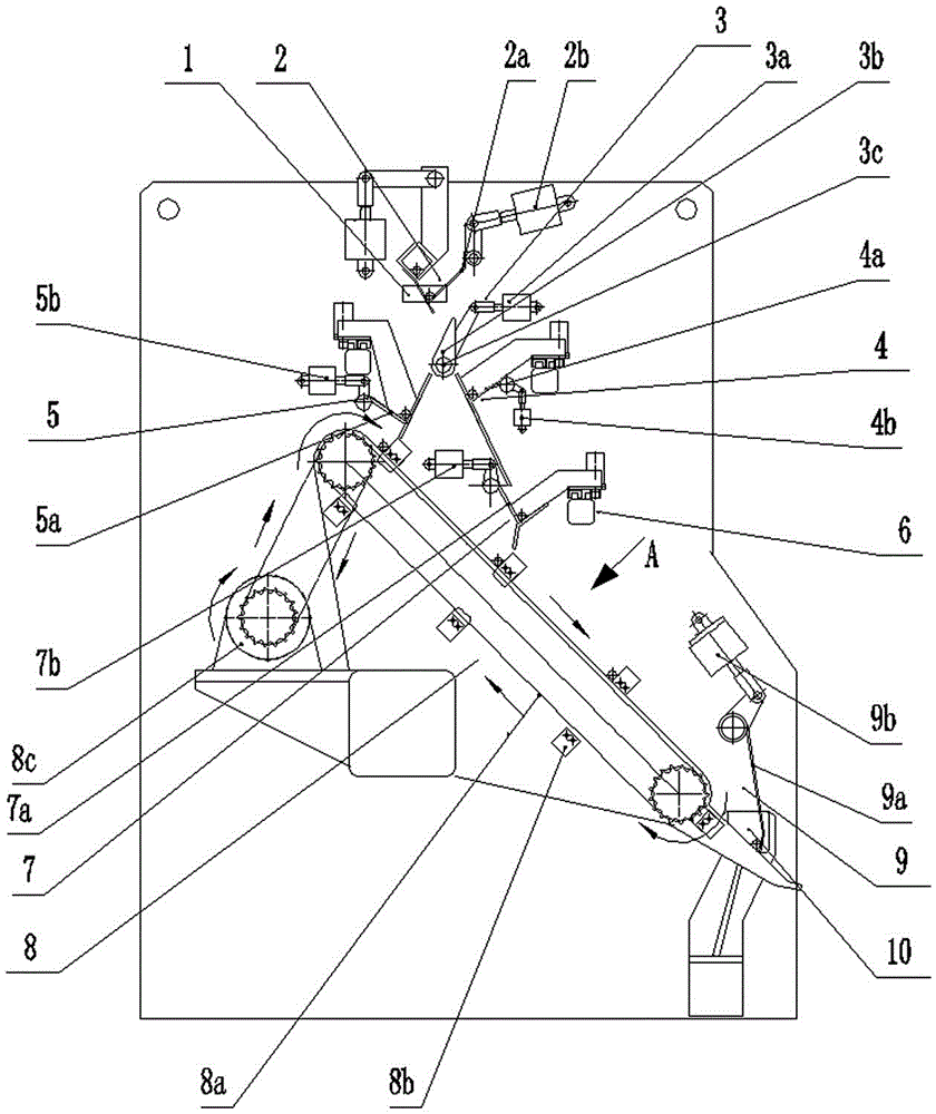
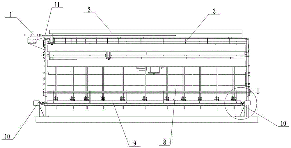
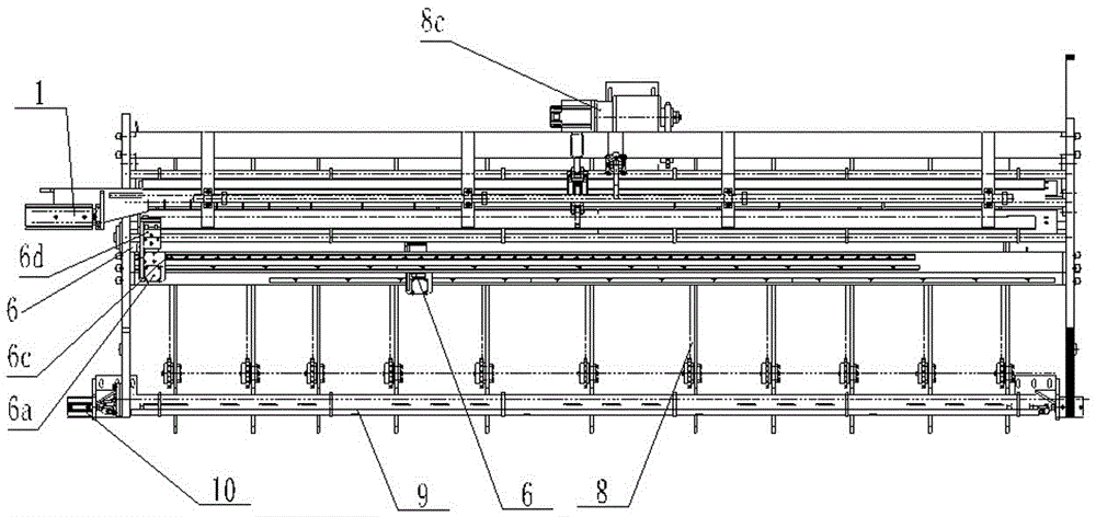
[0042] refer to Figure 1-Figure 3, a steel bar distributing device, including a feed bin 2 for receiving straightened steel bars, a conveying device 8 for transporting the steel bars, and an output bin 9 for outputting the steel bars to the main machine for forming the steel mesh. The material distribution device 3 of the material cylinder 3a, the material distribution plate 3b and the swing shaft 3c, the output end of the material distribution cylinder is connected with the swing shaft 3c, and the rotation of the swing shaft drives the material distribution plate 3b to swing, and the two sides below the material distribution plate 3b The first storage device 4 and the second storage device 5 are respectively arranged on the side, and the third storage device 7 is also arranged below the first storage device, and the first storage device, the second storage device and the third storage device are all configured with The steel bar laterally pushing device 6, the conveying devi...


PUM


Abstract

The invention provides a steel bar distributing device which comprises a feeding bin supporting a straightening steel bar, a conveying device transferring the steel bar, and a discharge bin outputting the steel bar to a steel bar mesh forming main machine, wherein a trimming air cylinder and trimming plate are arranged at the end of the feeding bin; a material distribution device comprising a material distribution air cylinder, a material distribution plate and a swing axle is arranged below the feeding bin; an output end of the material distribution air cylinder is connected with the swing axle; the swing axle rotates to drive the material distribution plate to swing; a first storage device and a second storage device are arranged on the two sides below the material distribution plate; a third storage device is further arranged below the first storage device; the first storage device, the second storage device and the third storage device are equipped with steel bar transverse pushing devices; and the conveying device comprises a transfer chain uniformly provided with material stopping plates. Through multilevel delivery, and after the steel bars are pushed transversely, the distributing device can realize automatic distribution of the multiple transverse bars in the same transverse bar position.

Description

technical field [0001] The invention relates to a reinforcement distributing device, in particular to a horizontal reinforcement distributing device and method for a reinforcement mesh forming machine. Background technique [0002] In recent years, with the vigorous development of the construction industry, welded steel mesh has been widely used in various cast-in-place concrete structural projects, and there are more and more steel meshes of different sizes and specifications. In order to meet the needs of high-efficiency and high-quality steel mesh production, The traditional method of manually binding or welding one by one to form a mesh has been gradually eliminated, and replaced by a highly automated steel mesh forming machine for production. [0003] However, at present, the steel mesh forming machine in our country can only process standard steel mesh (the length of the horizontal bar and the longitudinal bar are only one size), and the steel mesh that can be produced...

Claims


Application Information

Patent Timeline
Patent Type & Authority Patents(China)
IPC IPC(8): B21F23/00
Inventor 侯爱山赵红学王振丰肖飞刘子金张大鹏王辉汶浩纪恩龙贾晨光张东斌钟文海李生智岳巍巍翟小东
Owner CONSTR MECHANIZATION INST CHINESE ACAD OF ARCHITECTURE SCI
Learn More