Anti-earthquake-displacement bridge expansion joint device
An expansion joint, anti-seismic technology, used in bridges, bridge parts, bridge construction and other directions, can solve problems such as bearing falling off, support beam breakage, comb tooth breakage, etc., to extend service life, improve earthquake resistance, and avoid rigidity. damage effect
- Summary
- Abstract
- Description
- Claims
- Application Information
AI Technical Summary
Problems solved by technology
Method used
Image
Examples
Embodiment 1
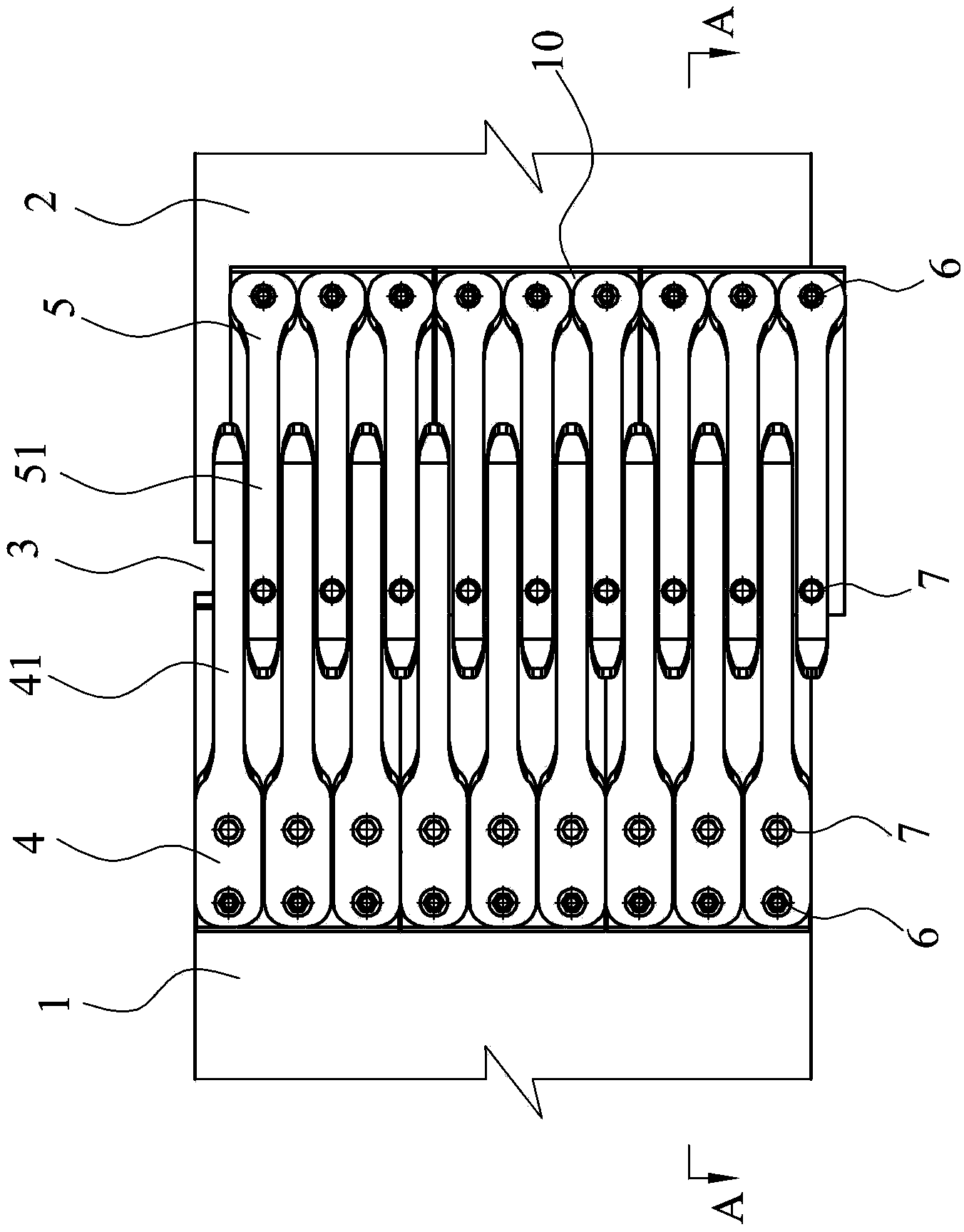
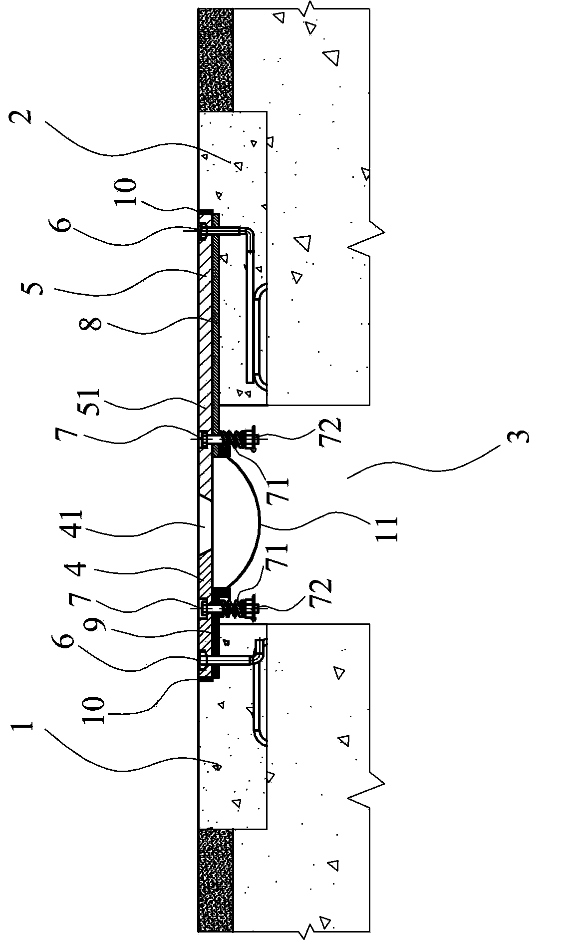
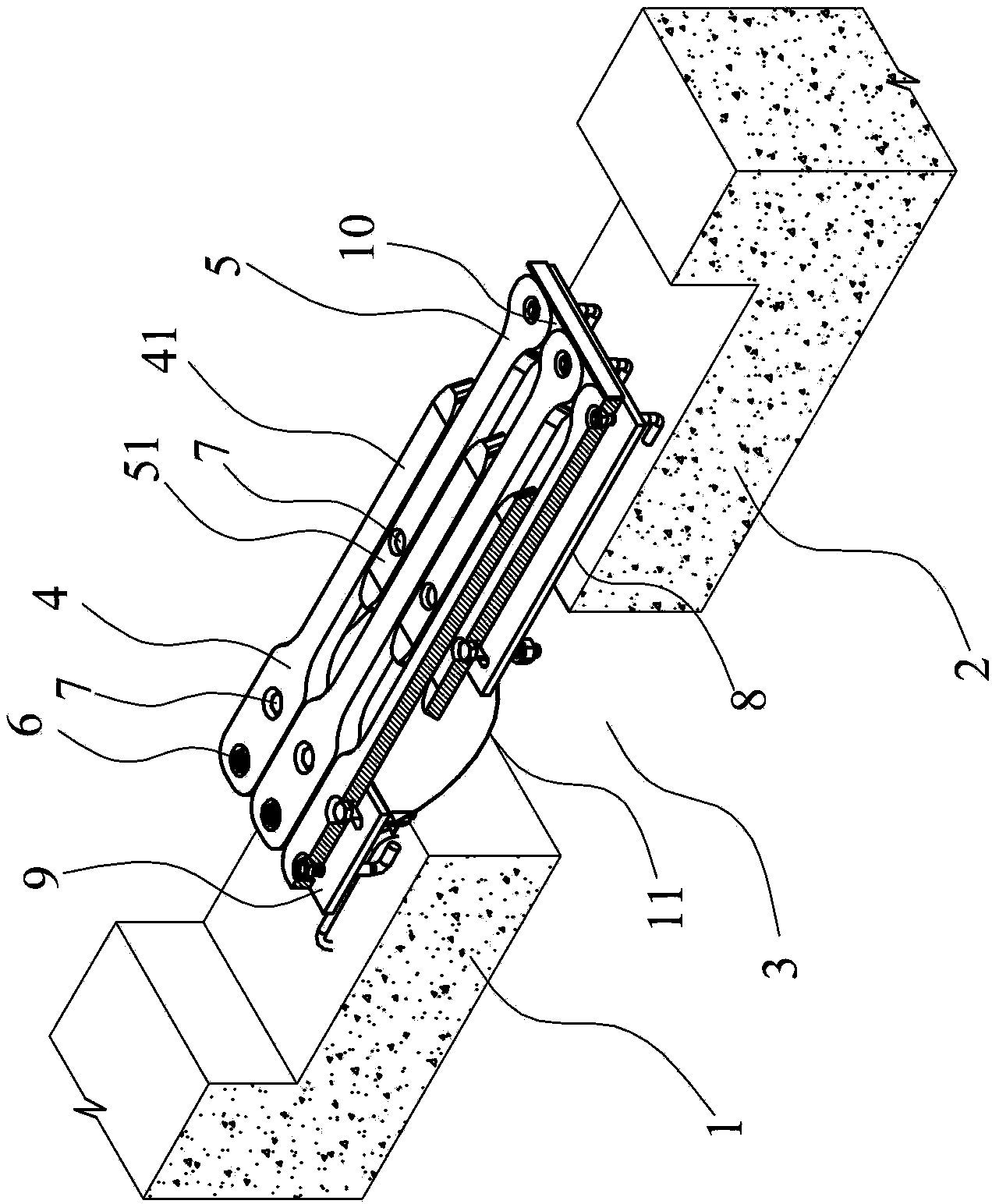
[0023] Such as Figure 1~5 As shown, the anti-seismic displacement bridge expansion joint device in the present embodiment includes a first movable comb 4 and a second movable comb respectively arranged on the first beam body 1 and the second beam body 2 on both sides of the bridge expansion joint 3 Comb plate 5, the first movable comb plate 4 and the second movable comb plate 5 are respectively provided with single comb teeth 41,51 at respective opposite ends and intersect each other at intervals, and the first movable comb plate 4 and the second movable comb plate 5 They are arranged on respective corresponding beam bodies 1 and 2 in a manner capable of lateral rotation relative to the beam bodies. Specifically: a first fixed bottom plate 9 is provided between the first movable comb plate 4 and the first beam body 1, and a fixing bolt 6 is arranged at the end of the first movable comb plate 4, and the fixing bolt 6 is arranged on the second 13 in the circular hole on the fi...
Embodiment 2
[0026] Such as Figure 6 and Figure 7 As shown, the bridge expansion joint device is different from Embodiment 1 in that: the first movable comb 4 and the second movable comb 5 are multi-comb type, specifically, the first movable comb 4 and the second movable comb The movable comb plate 5 has 3 comb teeth 41,51, and the 3 comb teeth 41,51 in each movable comb plate 4,5 are evenly arranged, and the comb teeth 41, 51 of the opposite movable comb plate 4,5, 51 cross intervals. The structure of the second fixed bottom plate 8 in embodiment 2 is as follows Figure 7 As shown, a round hole 13 is set in the middle of one end of the second fixed bottom plate 8, and three waist-shaped holes 12 are evenly set at the other end, corresponding to Figure 6 The fixed bolt 6 at the end of the second movable comb plate 5 and the rotating bolt 7 on the comb teeth, the structure of the first fixed bottom plate 9 is similar to that of the second fixed bottom plate 8, and will not be illustra...
PUM
 Abstract
Description
Claims
Application Information
 - R&D
- Intellectual Property
- Life Sciences
- Materials
- Tech Scout
- Unparalleled Data Quality
- Higher Quality Content
- 60% Fewer Hallucinations
Browse by: Latest US Patents, China's latest patents, Technical Efficacy Thesaurus, Application Domain, Technology Topic, Popular Technical Reports.
© 2025 PatSnap. All rights reserved.Legal|Privacy policy|Modern Slavery Act Transparency Statement|Sitemap|About US| Contact US: help@patsnap.com


