Ventilation type hog house

A ventilated, pig house technology, applied in the field of livestock and poultry houses, can solve the problems of unguaranteed sanitation conditions, waste residues, unfavorable pig activities, etc., and achieve the effects of comprehensive coverage, prevention of rigid damage, and improvement of ventilation performance.

Active Publication Date: 2018-11-06
河南恒旺盛源农牧股份有限公司
View PDF10 Cites 1 Cited by
  • Summary
  • Abstract
  • Description
  • Claims
  • Application Information

AI Technical Summary

Problems solved by technology

The disadvantage of the high hunger stock is that although it is set up to distinguish the feeding area, rest area, and excretion area, the inclined structure design is not conducive to the activities of pigs, and there is a problem of waste residues, and the sanitary conditions cannot be guaranteed
The disadvantage of this structure is: the structural design of the grid floor is only suitable for the feeding of adult pigs, and there is a risk of being stuck when feeding piglets

Method used


Image

  • Ventilation type hog house
  • Ventilation type hog house
  • Ventilation type hog house

Examples


Embodiment 1

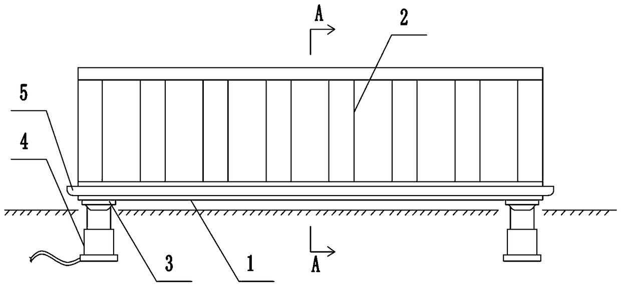
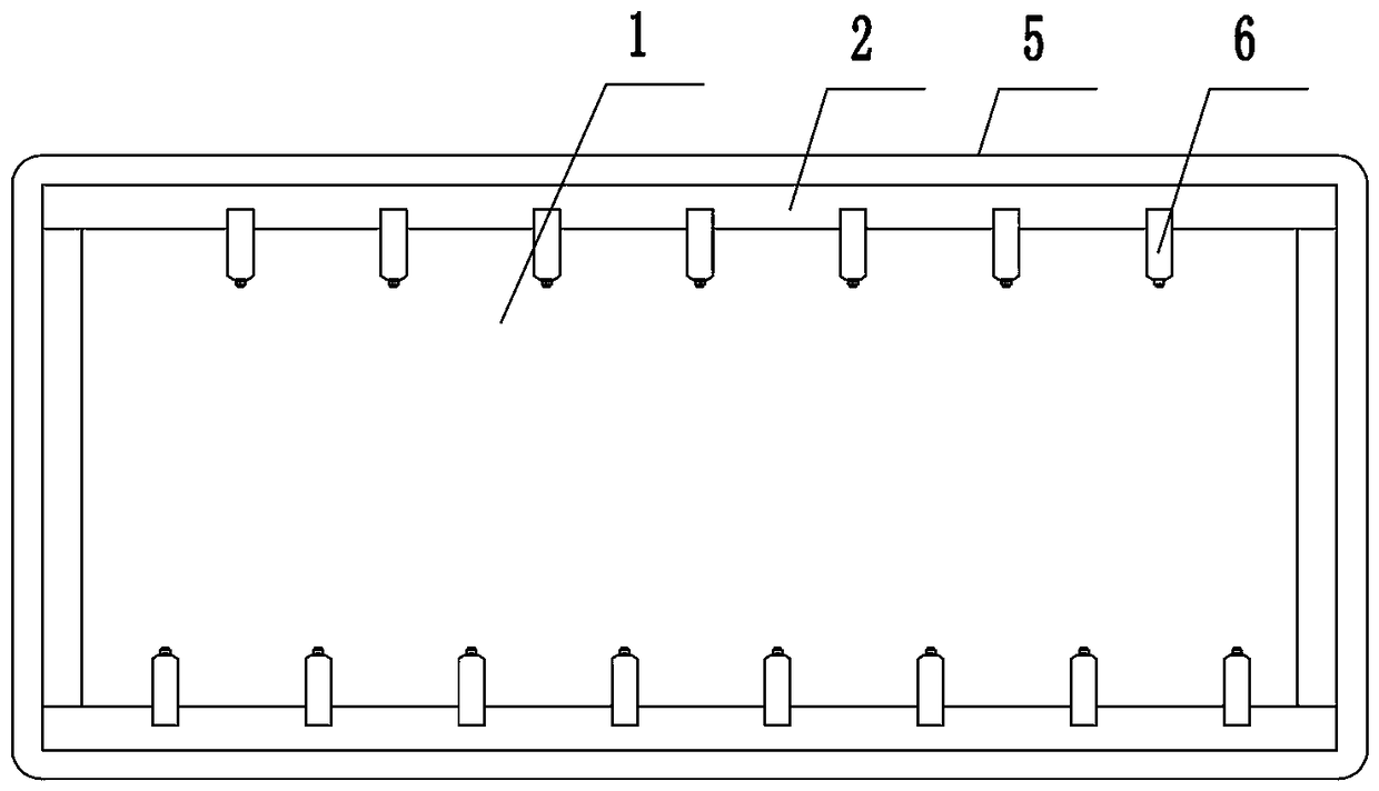
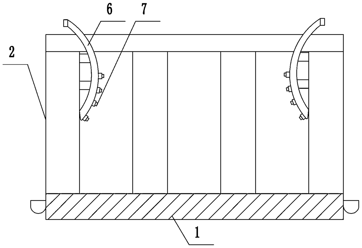
[0033] Such as Figure 1 to Figure 3 As shown, the present invention includes a base plate 1 and a fence 2, the base plate 1 and the fence 2 are welded by steel structure, a plurality of height adjustment mechanisms are arranged on the lower end surface of the base plate 1, and the height adjustment mechanism includes a hydraulic lifting mechanism and a connecting plate 3, a hydraulic pressure The lifting mechanism adopts the hydraulic lifting device of the prior art, including a hydraulic oil tank, an oil pump, a control valve and a telescopic cylinder 4. The base plate 1 is fixedly connected, the edge of the base plate 1 is fixedly provided with a chute 5, and the left and right sides of the fence 2 are provided with spray pipes 6. The spray pipe 6 is designed in an arc shape or inclined. The spray pipes 6 on the left and the spray pipes 6 on the right are arranged alternately in space.

Embodiment 2

[0035] The present invention includes a base plate 1 and a fence 2, the base plate 1 and the fence 2 are welded by steel structure, the lower end surface of the base plate 1 is provided with a plurality of height adjustment mechanisms, the height adjustment mechanism includes a hydraulic lifting mechanism and a connecting plate 3, and the hydraulic lifting mechanism adopts The hydraulic lifting device in the prior art includes a hydraulic oil tank, an oil pump, a control valve and a telescopic cylinder 4. The hydraulic telescopic mechanism is located under the ground, and the connection plate 3 is connected to the upper end of the telescopic cylinder 4 by a ball joint, and the connection plate 3 is fixed to the bottom plate 1. connection, the edge of the bottom plate 1 is fixedly provided with a chute 5, and the left and right sides of the fence 2 are provided with a spray pipe 6, the spray pipe 6 is an arc or inclined design, and a plurality of nozzles 7 are arranged on the spr...

Embodiment 3

[0038]The present invention includes a base plate 1 and a fence 2, the base plate 1 and the fence 2 adopt a steel structure and are plugged and fixed, the lower end surface of the base plate 1 is provided with a plurality of height adjustment mechanisms, and the height adjustment mechanism includes a hydraulic lifting mechanism and a connecting plate 3, a hydraulic lifting mechanism The hydraulic lifting device of the prior art is adopted, including a hydraulic oil tank, an oil pump, a control valve and a telescopic hydraulic cylinder 4. The hydraulic telescopic mechanism is located under the ground. Fixedly connected, the edge of the base plate 1 is fixedly provided with a chute 5, and the left and right sides of the fence 2 are provided with a spray pipe 6. The spray pipe 6 is designed to be curved or inclined. The shower pipe 6 on the right side and the shower pipe 6 on the right side are arranged alternately in space, and the fence 2 is a split structure.

[0039] The stru...


PUM


Abstract

The invention discloses a ventilation type hog house. The ventilation type hog house comprises a bottom plate and a fence. Multiple height adjusting mechanisms are arranged on the lower end face of the bottom plate, and comprise hydraulic lifting mechanisms and connecting plates, the connecting plates are hinged to the upper ends of the hydraulic lifting mechanisms and fixedly connected with the bottom plate, spraying pipes are arranged on the left side and the right side of the fence respectively, are designed to be in an arc shape or to be inclined, and are provided with multiple spraying nozzles, and the spraying pipes on the left side of the fence and the spraying pipes on the right side of the fence are staggered in space. The ventilation type hog house can be designed to be of different areas, and adapts to intensive modern feeding farms for using; by arranging the height adjusting mechanisms on the lower end of the bottom plate, the ventilation performance of the hog house is effectively improved, waste is prevented from being stacked and remaining, and the sanitary environment in the hog house is improved.

Description

technical field [0001] The invention belongs to the technical field of livestock and poultry houses, in particular to a ventilated pig house. Background technique [0002] Today's society is developing rapidly, and urban and rural construction is changing with each passing day. Pig farming is a long-term industry, so the construction of pig farms should conform to the development of the city. The sanitation and epidemic prevention conditions of traditional pig houses can no longer meet the current high requirements. Modern pig houses came into being under this condition. [0003] With the development of intensive and high-density feeding methods, more and more attention has been paid to environmental issues in pig farming. Practice has proved that the growth, health, reproduction, and feed utilization efficiency of pigs are all restricted by the pig house environment. The quality of environmental control such as temperature, humidity, air, and density is an important factor...

Claims


Application Information

Patent Timeline
Patent Type & Authority Applications(China)
IPC IPC(8): A01K1/02
CPCA01K1/02
Inventor 王付良
Owner 河南恒旺盛源农牧股份有限公司
Why Eureka
Try Eureka